Hi and thanks for using 2CarPros.com.
This can be a bit tricky because excessive slack on the chain can cause it to move the crank pulley. The chain should have three painted links (marks), one for each cam and one for the crank. Take your time and align colored links with the timing marks. The marks are positioned an exact number of links between each. Once you get all of them to align, it will be good.
Here are the directions specific to your vehicle and this job. It explains everything in detail. All attached pictures correlate with these directions.
________________________________________
PROCEDURES
REMOVAL
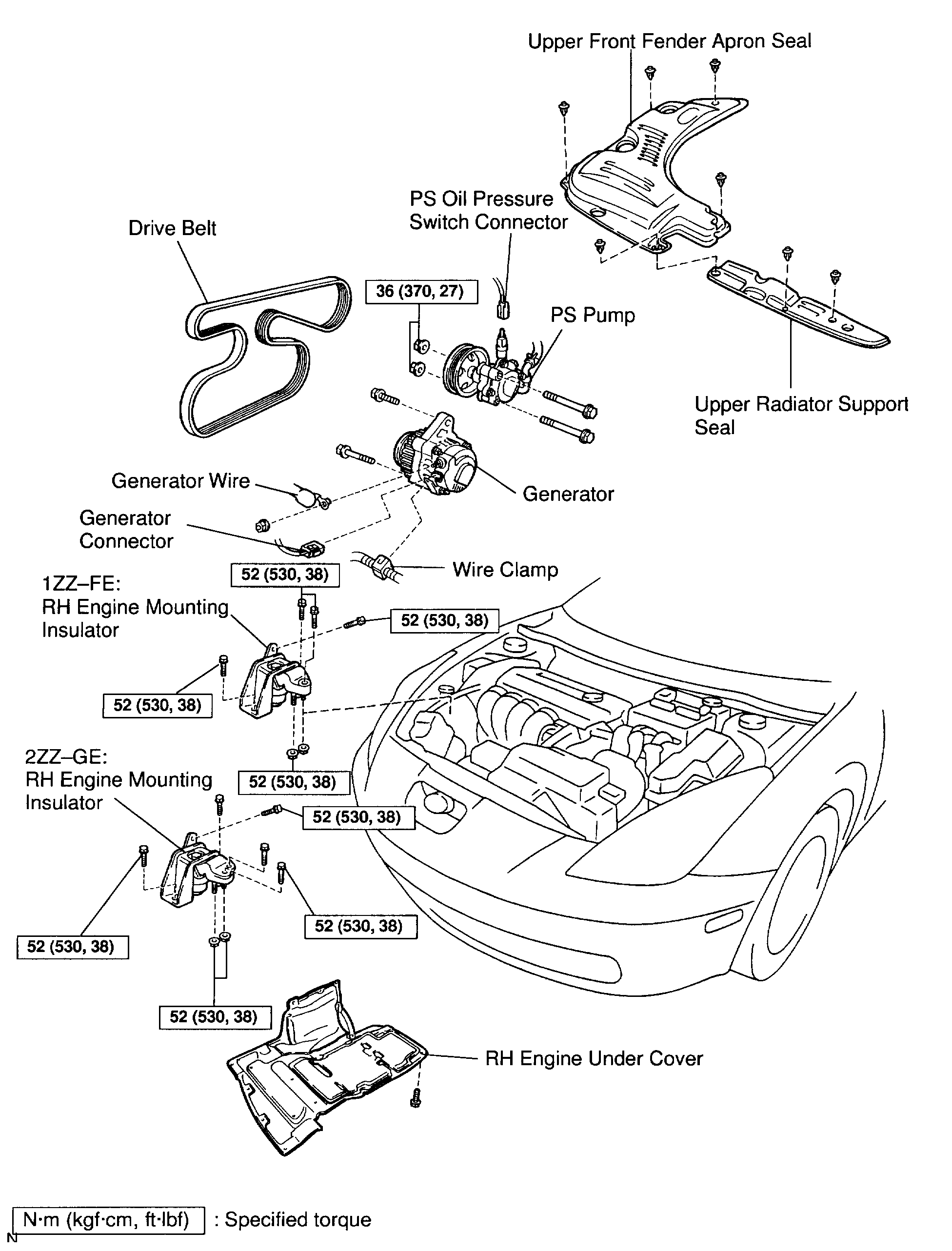
1. REMOVE UPPER FRONT FENDER APRON SEAL AND UPPER RADIATOR SUPPORT SEAL
2. DRAIN ENGINE COOLANT
3. REMOVE RH FRONT WHEEL
4. REMOVE RH ENGINE UNDER COVER
5. REMOVE DRIVE BELT AND GENERATOR
6. DISCONNECT PS PUMP FROM ENGINE
a. Disconnect the PS oil pressure switch connector.
b. Remove the 2 nuts and through bolts, and disconnect the PS pump from the engine.
HINT: Put aside the pump and suspend it to the cowl with a string.
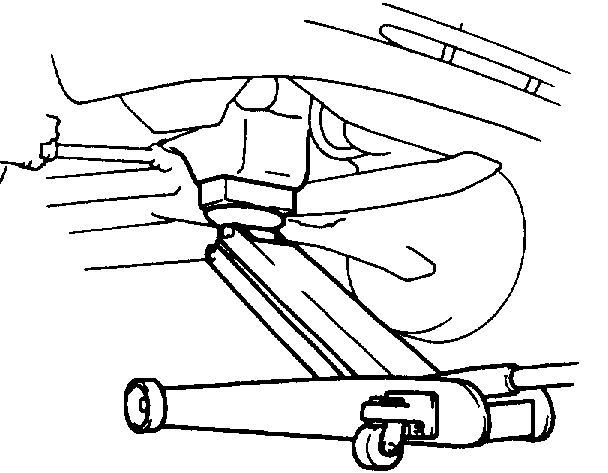
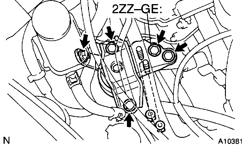
7. REMOVE RH ENGINE MOUNTING INSULATOR
a. Set the jack to the engine.
HINT: Place a wooden block between the jack and engine.
b. 1ZZ-FE: Remove the 4 bolts, 2 nuts and RH engine mounting insulator.
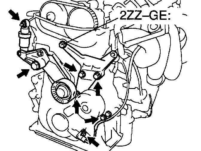
c. 2ZZ-GE: Remove the 5 bolts, 2 nuts and RH engine mounting insulator.
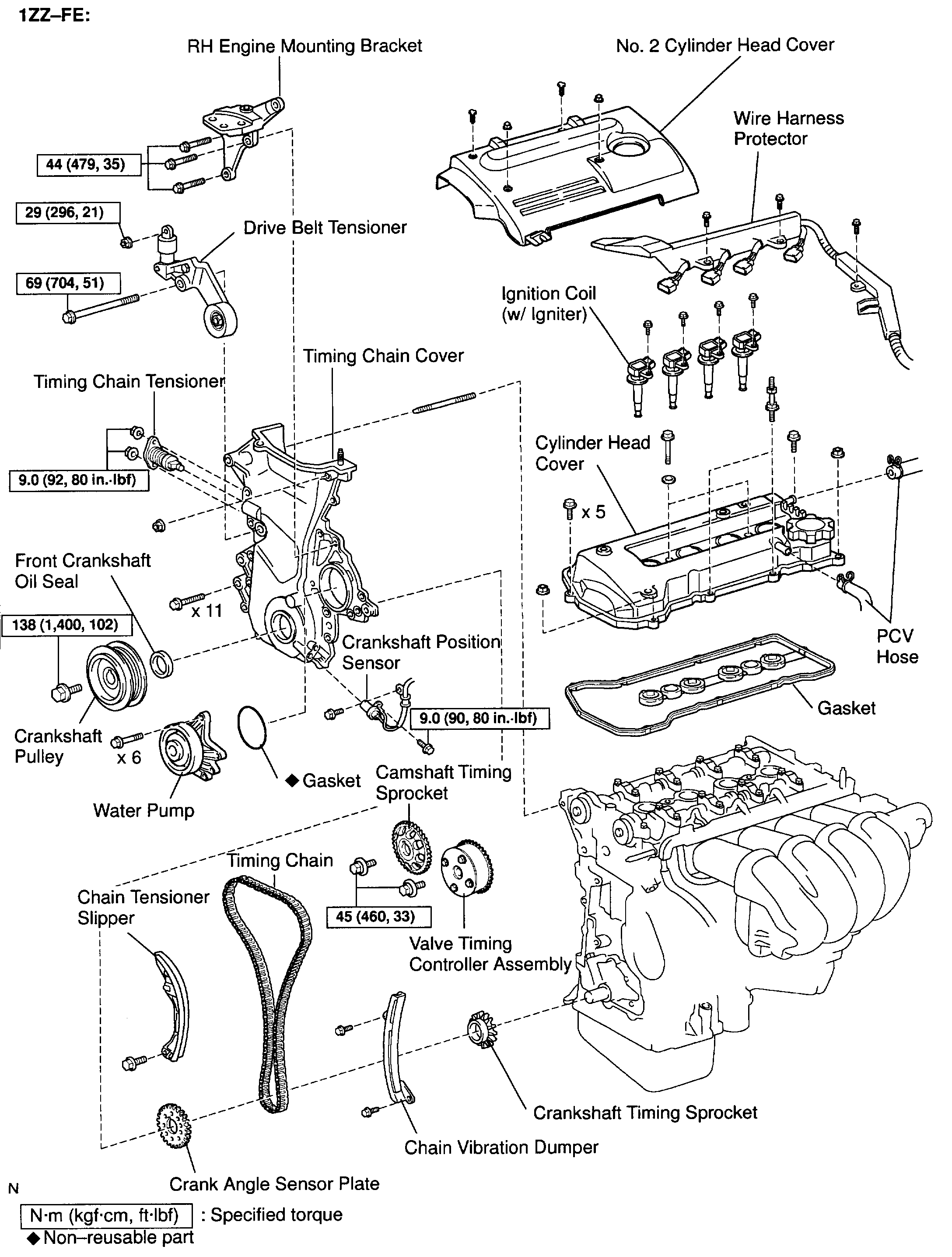
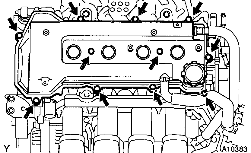
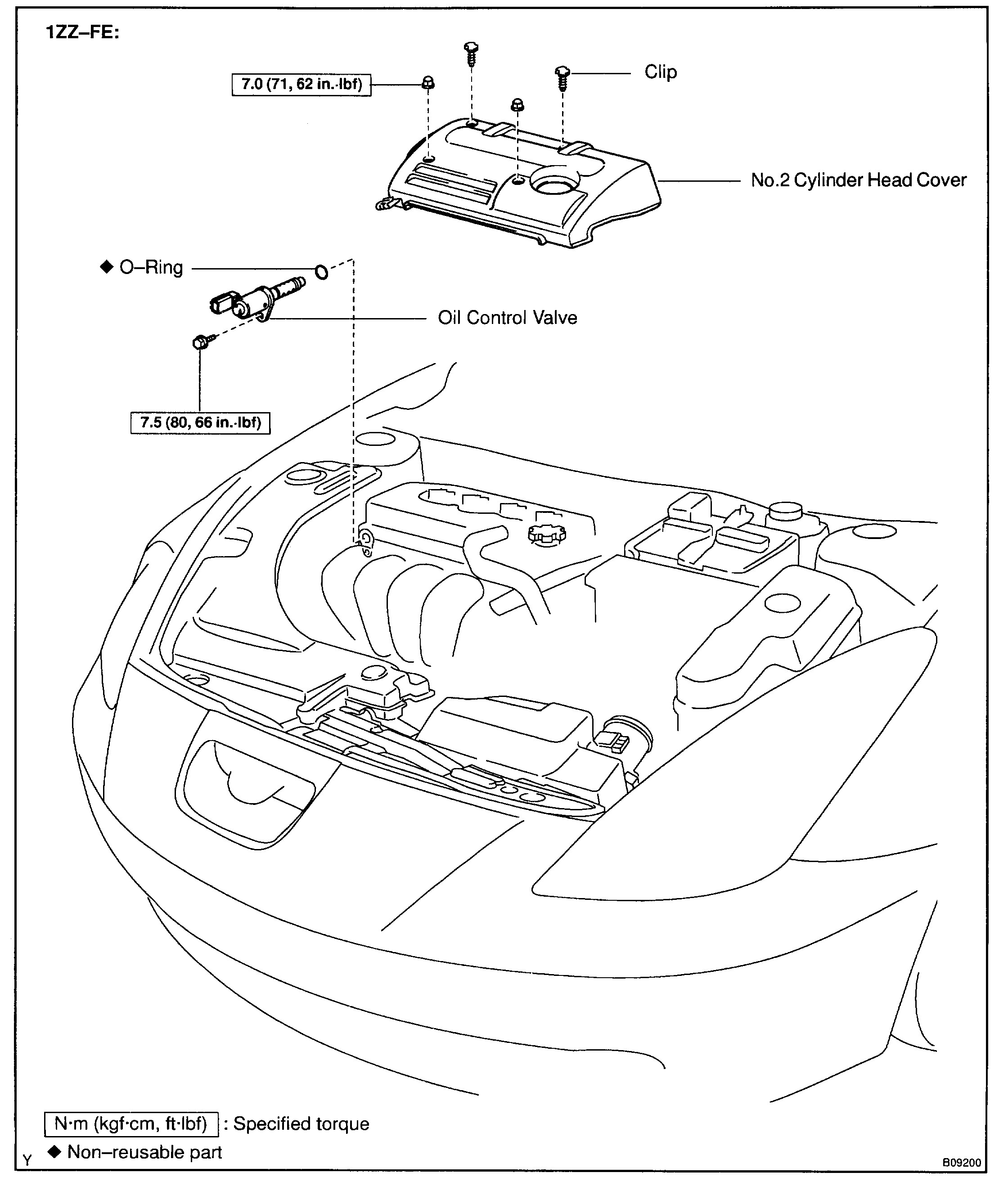
8. 1ZZ-FE: REMOVE CYLINDER HEAD COVER
a. Remove the 4 bolts and No. 2 cylinder head cover.
b. Remove the 4 ignition coils.
c. Disconnect the 2 PCV hoses from the cylinder head.
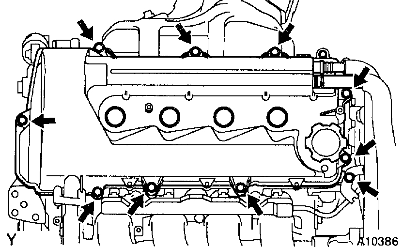
d. Remove the 9 bolts, 2 seal washers, 2 nuts, cylinder head cover and gasket.
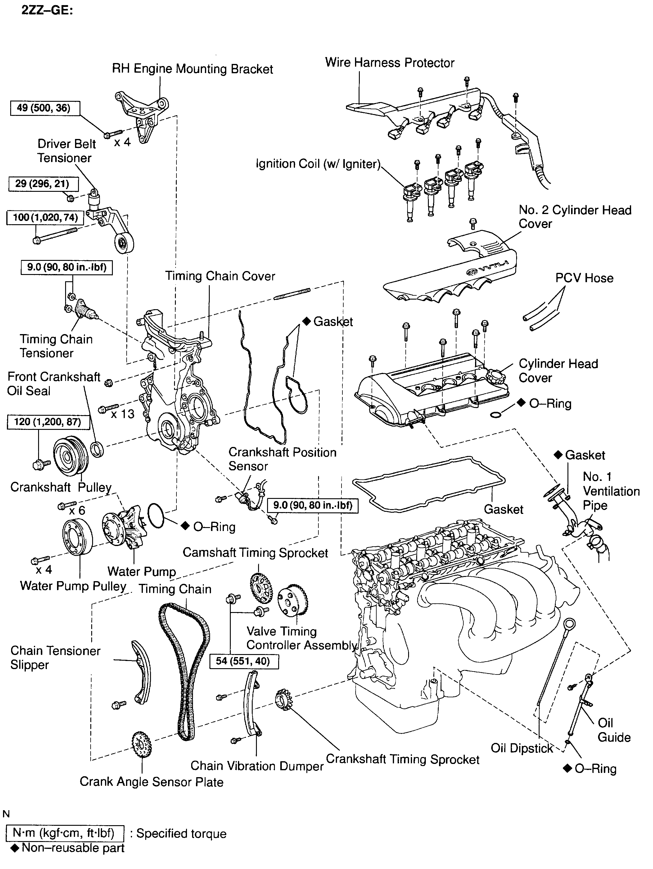
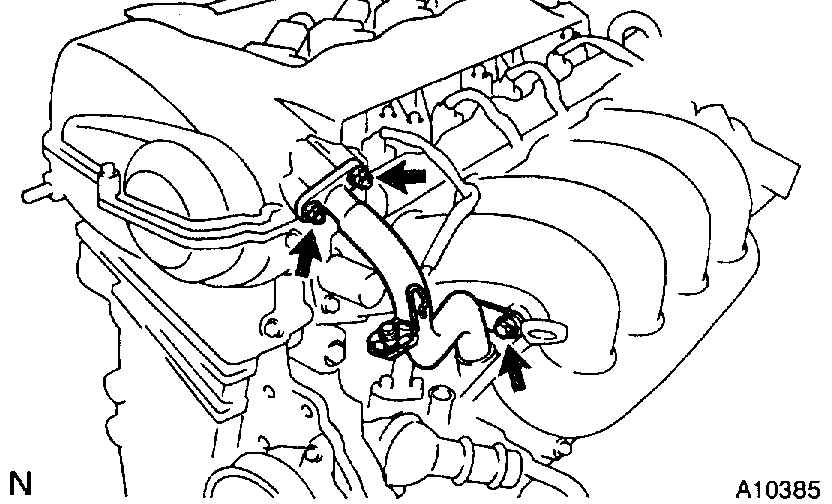
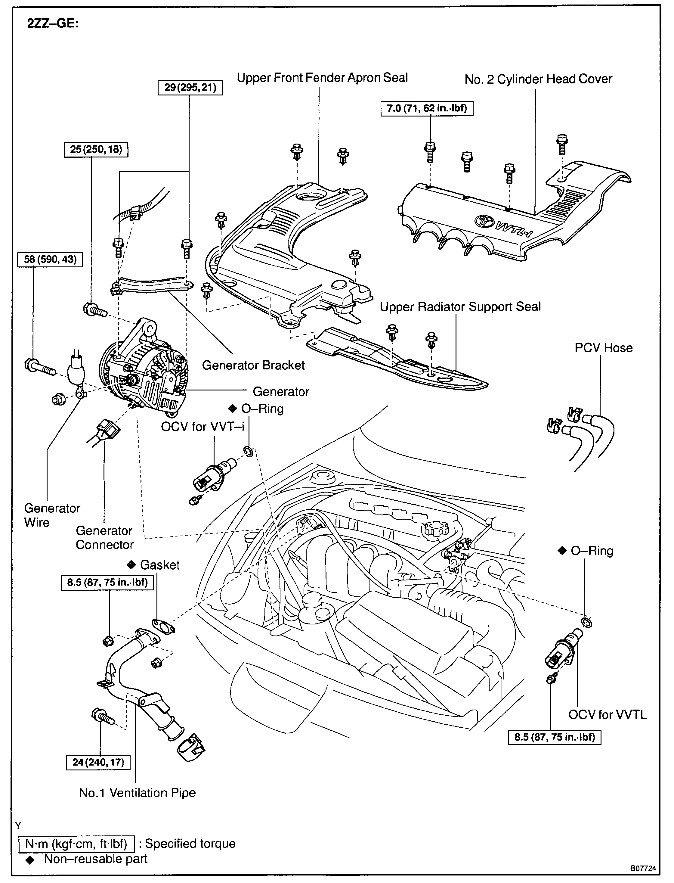
9. 2ZZ-GE: REMOVE CYLINDER HEAD COVER
a. Remove the 4 bolts and No. 2 cylinder head cover.
b. Remove the ignition coils.
c. Disconnect the 2 PCV hoses from the cylinder head cover.
d. Remove the 2 nuts, bolt and disconnect the No. 3 ventilation hose from the No. 1 ventilation pipe.
e. Remove the No. 1 ventilation pipe and gasket.
f. Remove the 9 bolts, wire harness protector, cylinder head cover and gasket.
g. Remove the O-ring from the cylinder head cover.
10. SET NO. 1 CYLINDER TO TDC/COMPRESSION
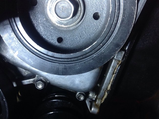
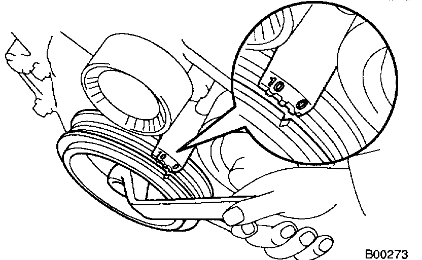
a. Turn the crankshaft pulley, and align its groove with timing mark "0" of the timing chain cover.
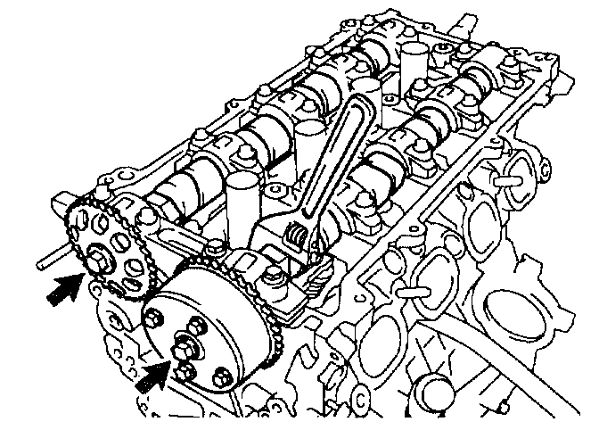
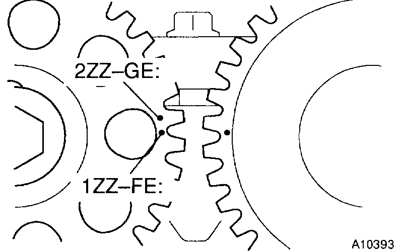
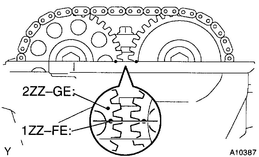
b. Check that the point marks of the camshaft timing sprockets are in straight line on the timing chain cover surface as shown in the illustration.
If not, turn the crankshaft 1 revolution (360°) and align the marks.
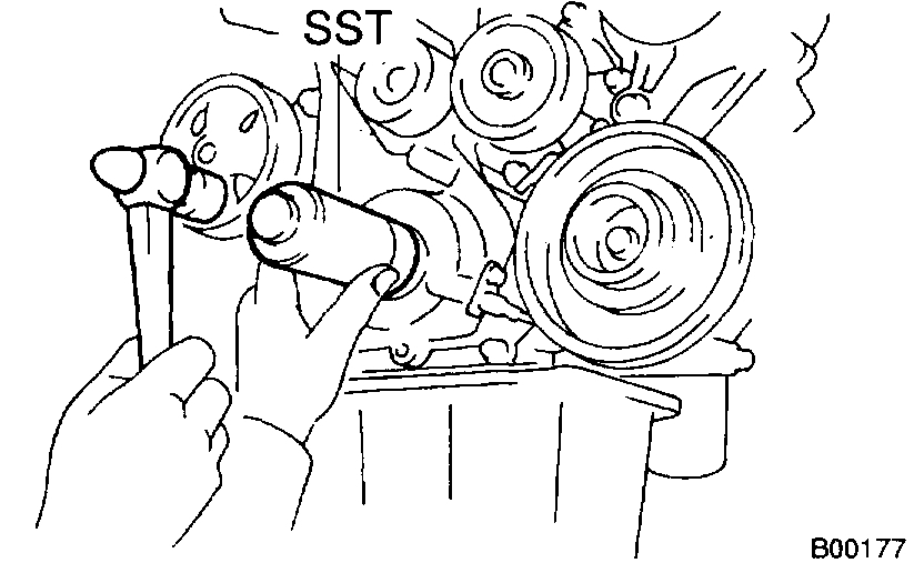
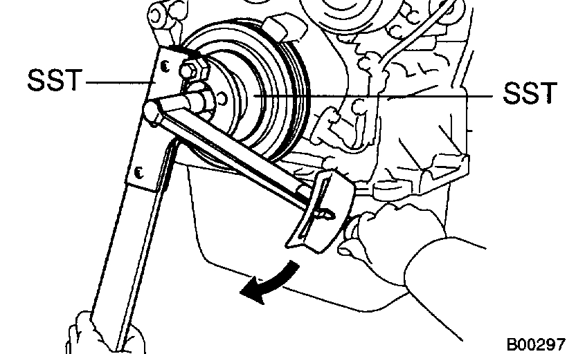
11. REMOVE CRANKSHAFT PULLEY
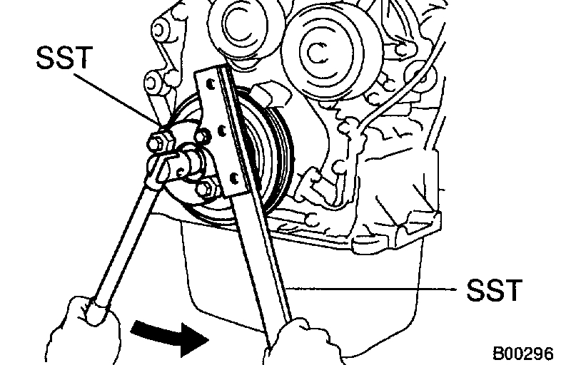
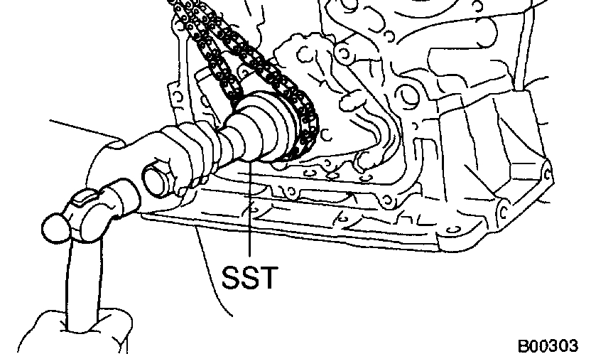
a. Using SST and 2 nuts (width: 10 mm (0.25 inch)), remove the pulley bolt.
SST 09213-70010, 09330-00021
b. Remove the crankshaft pulley.
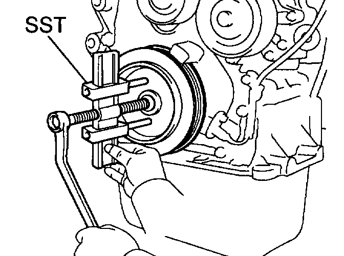
HINT: If necessary, remove the pulley with SST.
SST 09950-50012 (09951-05010, 09952-05010, 09953-05020, 09954-05020)
12. DISCONNECT CRANKSHAFT POSITION SENSOR FROM TIMING CHAIN COVER
Remove the 2 bolts and crankshaft position sensor.
13. REMOVE DRIVE BELT TENSIONER
Remove the bolt, nut and drive belt tensioner.
14. REMOVE RH ENGINE MOUNTING BRACKET
a. 1ZZ-FE: Remove the 3 bolts and mounting bracket.
b. 2ZZ-GE: Remove the 4 bolts and mounting bracket.
15. REMOVE CHAIN TENSIONER
Remove the 2 nuts and chain tensioner.
16. REMOVE WATER PUMP
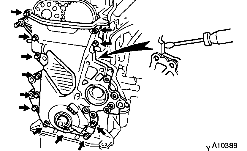
17. 1ZZ-FE: REMOVE TIMING CHAIN COVER
a. Remove the 11 bolts and nut.
b. Using a torx wrench socket (E8), remove the stud bolt.
c. Remove the timing chain cover by prying the portions between the cylinder head and cylinder block with a screwdriver.
NOTICE: Be careful not to damage the contact surfaces of the timing chain cover, cylinder head and cylinder block.
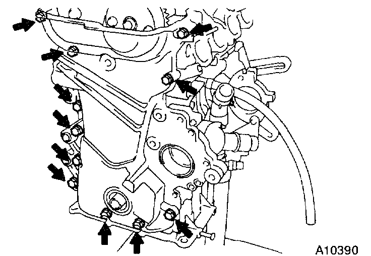
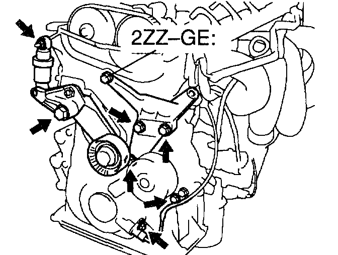
18. 2ZZ-GE: REMOVE TIMING CHAIN COVER
a. Remove the 12 bolts.
b. Using a torx wrench socket (E8), remove the stud bolt.
c. Remove the timing chain cover and 2 gaskets.
19. REMOVE CRANK ANGLE SENSOR PLATE
20. REMOVE CHAIN TENSIONER SLIPPER
Remove the bolt and slipper.
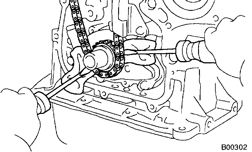
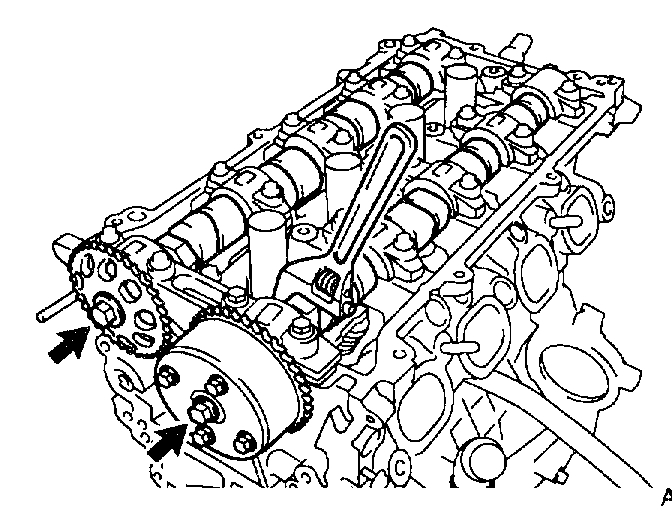
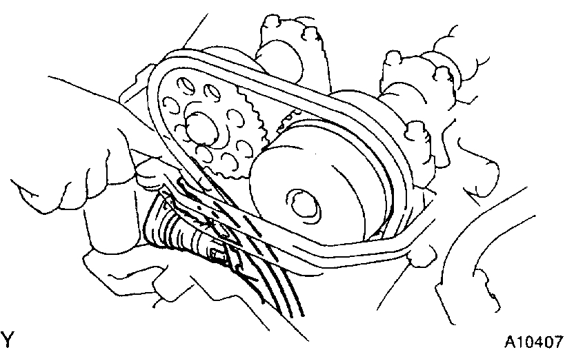
21. REMOVE TIMING CHAIN AND CRANKSHAFT TIMING SPROCKET
If the crankshaft timing sprocket cannot be removed by hand, use 2 screwdrivers.
NOTICE: Position shop rags as shown to prevent damage.
22. REMOVE CHAIN VIBRATION DAMPER
Remove the 2 bolts and damper.
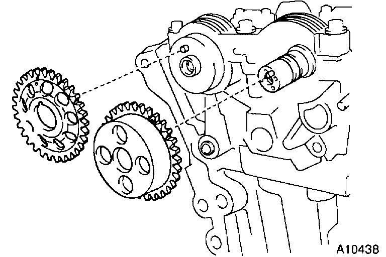
23. REMOVE VALVE TIMING CONTROL ASSEMBLY AND CAMSHAFT TIMING SPROCKET
Hold the hexagonal head wrench portion of the camshaft with a wrench, and remove the bolt, valve timing controller assembly and timing sprocket.
NOTICE:
- Be careful not to damage the cylinder head and valve lifter with the wrench.
- Do not disassemble the valve timing controller assembly.
INSPECTION
1. INSPECT TIMING CHAIN AND TIMING SPROCKETS
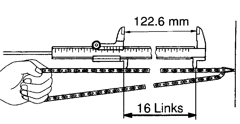
a. Using a vernier calipers, measure the length of 16 links with the chain dully stretched.
Maximum chain elongation: 122.6 mm (4.827 inch)
If the elongation is greater than maximum, replace the chain.
HINT: Make the same measurements pulling at 3 or more places selected at random.
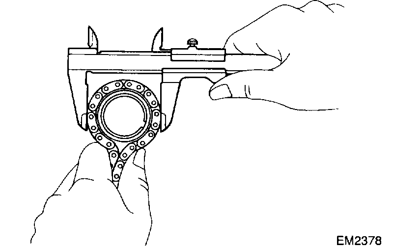
b. Wrap the chain around the timing sprocket.
c. Using a vernier calipers, measure the timing sprocket diameter with the chain.
NOTICE: Vernier calipers must contact the chain rollers for measuring.
Minimum sprocket diameter (w/ Chain):
Camshaft 97.3 mm (3.831 inch)
Crankshaft 51.6 mm (2.031 inch)
If the diameter is less than minimum, replace the chain and sprockets.
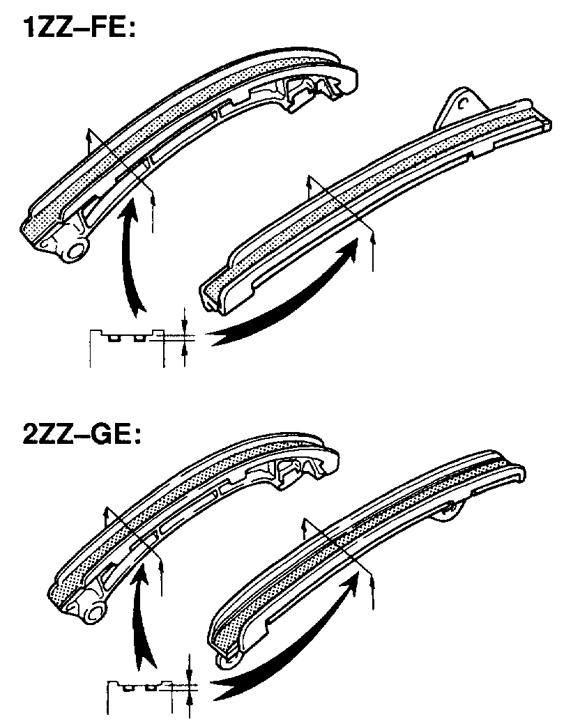
2. INSPECT CHAIN TENSIONER SLIPPER AND VIBRATION DAMPER
Measure the chain tensioner slipper and vibration damper wears.
Maximum wear: 1.0 mm (0.039 inch)
If the wear is greater than maximum, replace the slipper and/or damper.
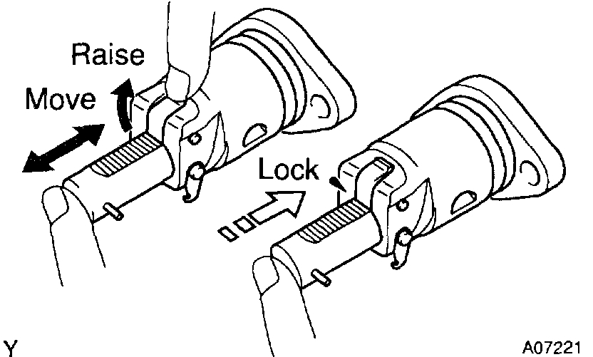
3. INSPECT CHAIN TENSIONER
a. Check that the plunger moves smoothly when the ratchet pawl is raised with your finger.
b. Release the ratchet pawl and check that the plunger is locked in place by the ratchet pawl and does not move when pushed with your finger.
4. INSPECT OIL JET
REPLACEMENT
HINT: There are 2 methods (A and B) to replace the oil seal which are as follows:
REPLACE CRANKSHAFT FRONT OIL SEAL
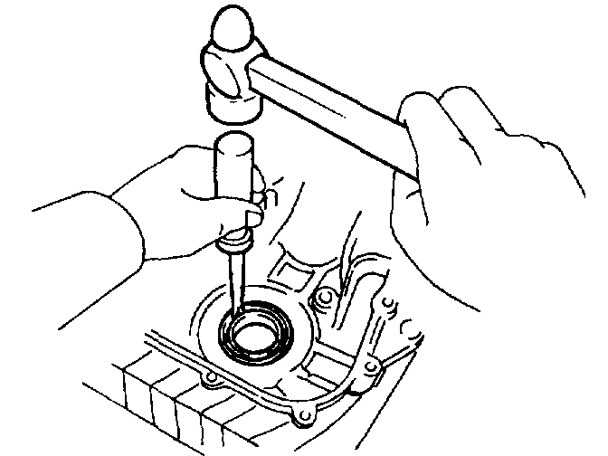
a. If timing chain cover is removed from cylinder block.
1. Using a screwdriver and a hammer, tap out the oil seal.
2. Using SST and a hammer, tap in a new oil seal until its surface is flush with the timing chain cover edge.
SST 09309-37010
3. Apply MP grease to the oil seal lip.
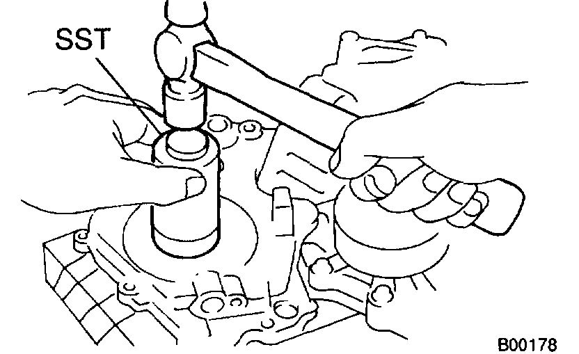
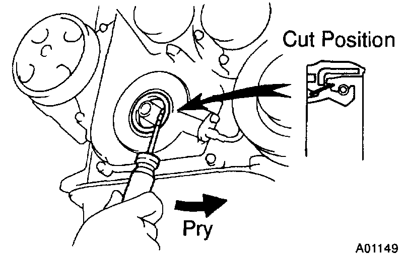
b. If timing chain cover is installed to the cylinder block.
1. Using a knife, cut off the oil seal lip.
2. Using a screwdriver, pry out the oil seal.
NOTICE: Be careful not to damage the crankshaft. Tape the screwdriver tip.
3. Using SST and a hammer, tap in the oil seal until its surface is flush with the timing chain cover edge.
SST 09309-37010
INSTALLATION
1. INSTALL VALVE TIMING CONTROLLER ASSEMBLY AND CAMSHAFT TIMING SPROCKET
a. Apply engine oil in the range from the tip of the intake camshaft to 16 mm from that tip.
b. Align the timing mark on the value timing controller assembly with the knock pin, and install the value timing controller assembly to the cam shaft.
NOTICE: Do not push valve timing controller assembly to the camshaft forcibly when installing it.
c. Align the knock pin hole in the cam shaft timing sprocket with the knock pin of the cam shaft, and exhaust the sprocket to the camshaft.
d. Temporarily install the timing sprocket bolt.
e. Hold the hexagon wrench head portion of the camshaft with a wrench, and tighten the timing sprocket bolt.
Torque:
1ZZ-FE 45 Nm (460 kgf-cm, 33 ft. lbs.)
2ZZ-GE 54 Nm (551 kgf-cm, 40 ft. lbs.)
2. SET NO. 1 CYLINDER TO TDC/COMPRESSION
a. Turn the hexagonal wrench head portion of the camshafts, and align the point marks of the camshaft timing sprockets.
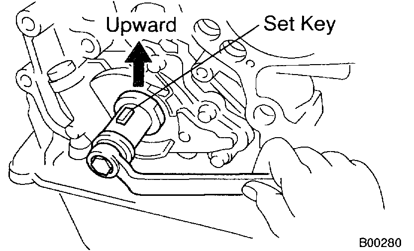
b. Using a crankshaft pulley bolt, Turn the crankshaft and set the set key on the crankshaft upward.
3. INSTALL CHAIN VIBRATION DAMPER
Install the damper with the 2 bolts.
Torque:
1ZZ-FE 11 Nm(113 kgf-cm, 8 ft. lbs.)
2ZZ-GE 20.5 Nm (209 kgf-cm, 15 ft. lbs.)
4. INSTALL TIMING CHAIN AND CRANKSHAFT TIMING SPROCKET
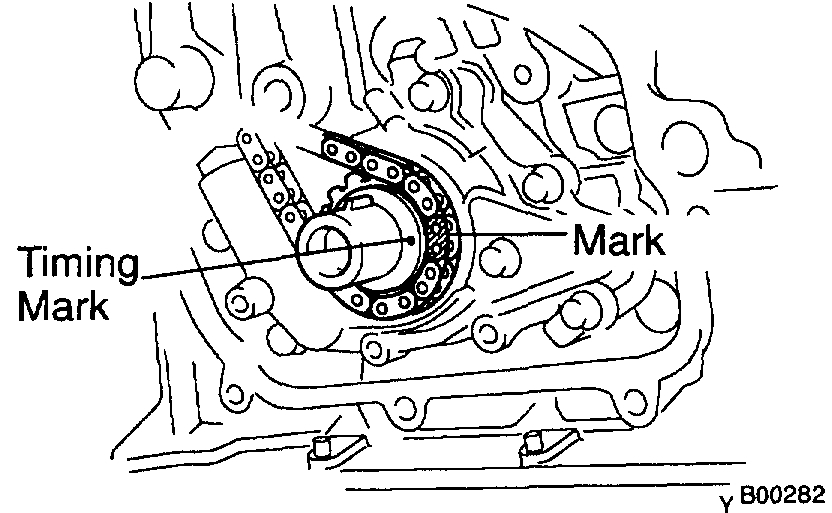
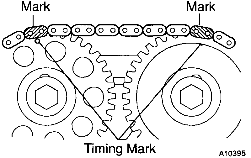
a. Install the timing chain on the crankshaft timing sprocket with the yellow color link aligned with the timing mark on the crankshaft timing sprocket.
HINT: If necessary, install the sprocket with SST.
SST 09223-22010
b. 1ZZ-FE: Install the timing chain on the camshaft timing sprockets with the yellow color links aligned with the timing marks on the camshaft timing sprockets.
c. 2ZZ-GE: Install the timing chain on the camshaft timing sprockets with the orange color links aligned with the timing marks on the camshaft timing sprockets.
d. Check that the tension between the intake camshaft timing sprocket and crankshaft timing sprocket.
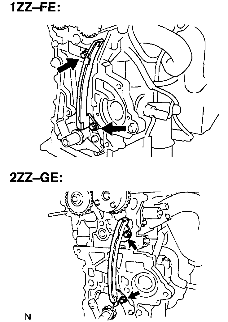
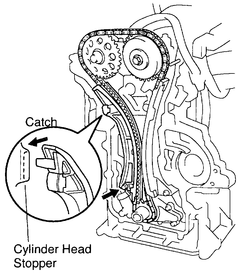
5. INSTALL CHAIN TENSIONER SLIPPER
a. Install the slipper with the bolt.
Torque:
1ZZ-FE 18.5 Nm (189 kgf-cm, 14 ft. lbs.)
2ZZ-GE 20.5 Nm (209 kgf-cm, 15 ft. lbs.)
b. Check that the slipper moves is caught on the cylinder head stopper.
NOTICE: DO not turn the crankshaft.
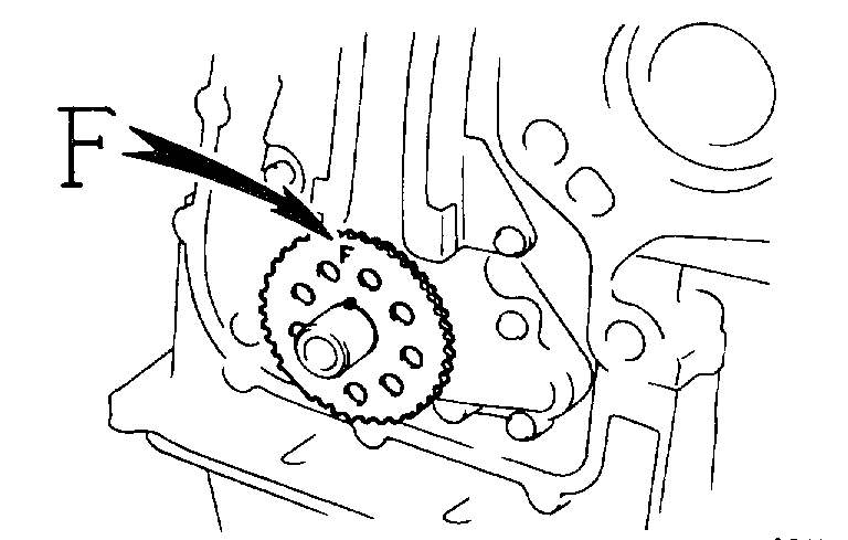
6. INSTALL CRANK ANGLE SENSOR PLATE
Install the plate with the "F" mark facing forward.
7. 1ZZ-FE: INSTALL TIMING CHAIN COVER AND WATER PUMP
a. Remove any old packing (FIPG) material and be careful not to drop any oil on the contact surfaces of the timing chain cover, cylinder head and cylinder block.
- Using a razor blade and a gasket scraper, remove all the old packing (FIPG) material from the gasket surfaces and sealing grooves.
- Thoroughly clean all components to remove all the loose material.
- Using a non-residue solvent, clean both sealing surfaces.
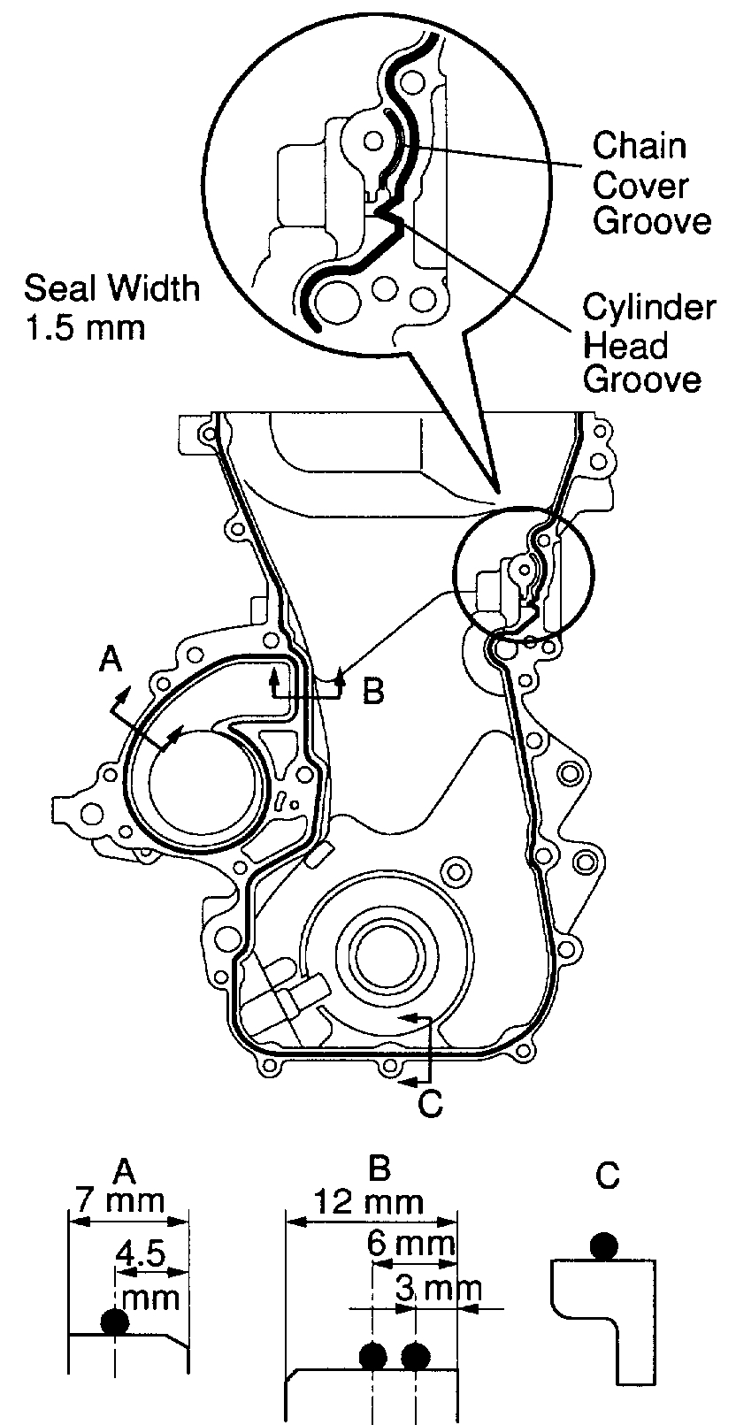
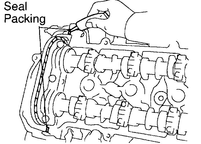
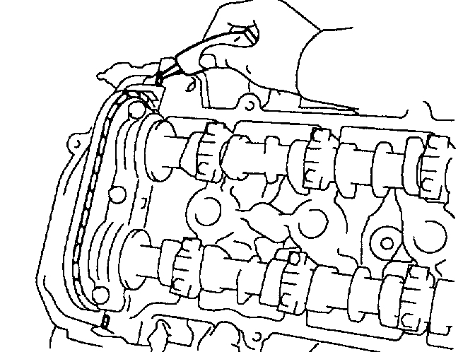
b. Apply seal packing to the timing chain cover as shown in the illustration.
Seal packing: Part No. 08826-00100 or equivalent
- Install a nozzle that has been cut to a 1.5 mm (0.16 - 0.20 inch) opening.
HINT: Avoid applying an excessive amount to the surface.
- Parts must be assembled within 3 minutes of application. Otherwise the material must be removed and reapplied.
- Immediately remove nozzle from the tube and reinstall cap.
c. Apply seal packing to 2 locations as shown in the illustration.
Seal packing: Part No. 08826-00080 or equivalent
- Install a nozzle that has been cut to a 1.5 mm (0.16 - 0.20 inch) opening.
HINT: Avoid applying an excessive amount to the surface.
- Parts must be assembled within 3 minutes of application. Otherwise the material must be removed and reapplied.
- Immediately remove nozzle from the tube and reinstall cap.
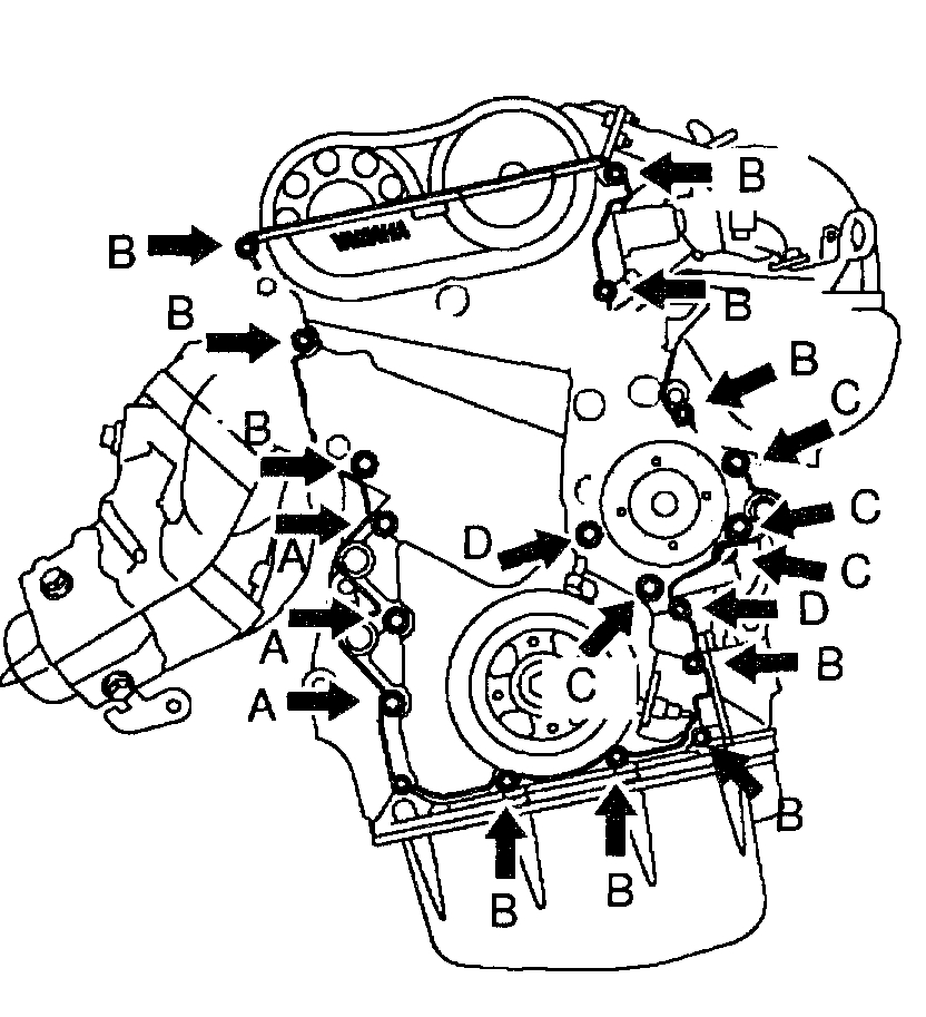
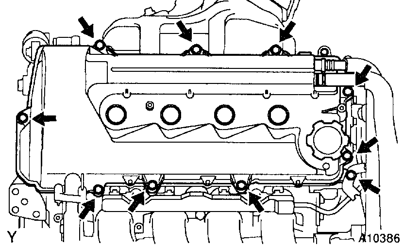
d. Install the timing chain cover, O-ring and water pump with the 17 bolts and nut. Uniformly tighten the bolts and nut in several passes.
Torque:
10 mm head:
9 Nm (92 kgf-cm, 80 inch lbs.) for C
13 Nm (133 kgf-cm, 10 ft. lbs.) for A
11 Nm (113 kgf-cm, 8 ft. lbs.) for others
12 mm head: 18.5 Nm (189 kgf-cm, 14 ft. lbs.)
NOTICE:
- Pay attention not to wrap the chain and slipper over the chain cover seal line.
- After installing the chain cover, must install the mounting bracket and water pump within 15 minutes.
HINT: Each bolt length in indicated in the illustration.
A 45 mm (1.77 inch)
B 35 mm (1.38 inch)
C 30 mm (1.18 inch)
D 25 mm (0.98 inch)
e. Using a torx wench socket (E8), install the stud bolt.
Torque: 9.3 Nm (95 kgf-cm, 82 inch lbs.)
8. 2ZZ-E: INSTALL TIMING CHAIN COVER AND WATER PUMP
a. Remove any old packing (FIPG) material and be careful not to drop any oil on the contact surfaces of the timing chain cover, cylinder head and cylinder block.
- Using a razor blade and a gasket scraper, remove all the old packing (FIPG) material from the gasket surfaces and sealing grooves.
- Thoroughly clean all components to remove all the loose material.
- Using a non-residue solvent, clean both sealing surfaces.
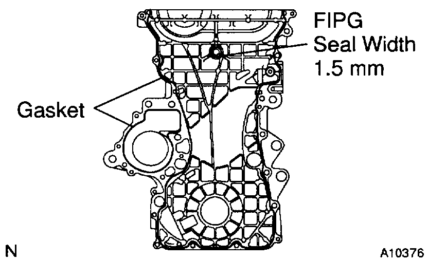
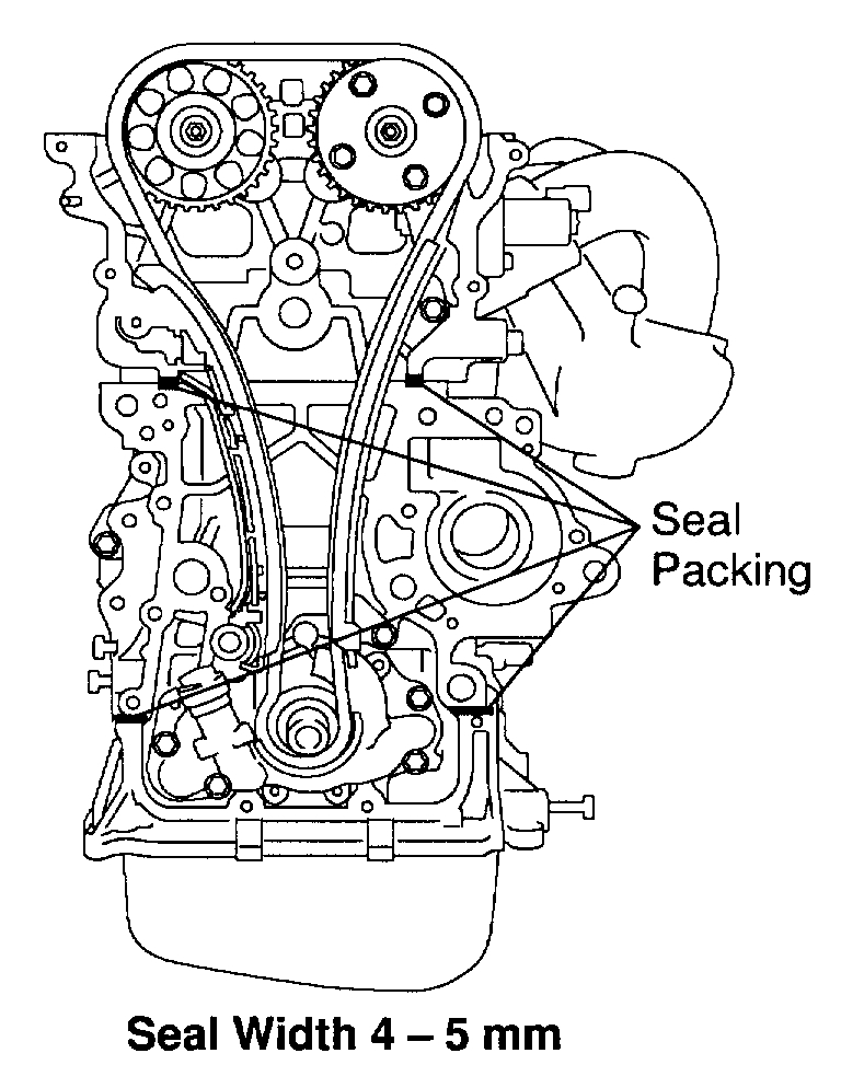
b. Apply seal packing to the timing chain cover as shown in the illustration.
Seal packing: Part No. 08826-00100 or equivalent
- Install a nozzle that has been cut to a 1.5 mm opening.
HINT: Avoid applying an excessive amount to the surface.
- Parts must be assembled within 3 minutes of application. Otherwise the material must be removed and reapplied.
- Immediately remove nozzle from the tube and reinstall cap.
c. Install the 2 gasket to the timing chain cover as shown in the illustration.
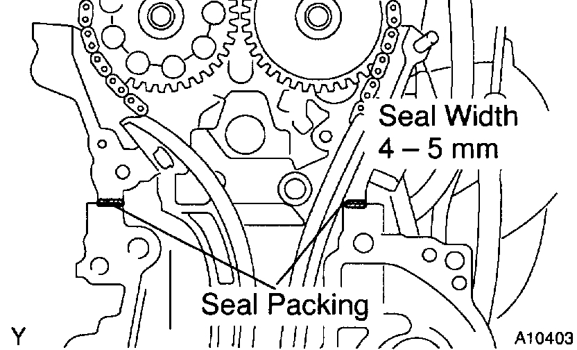
d. Apply seal packing to 4 locations as shown in the illustration.
Seal packing: Part No. 08826-00080 or equivalent
- Install a nozzle that has been cut to a 4 - 5 mm (0.16 - 0.20 inch) opening.
HINT: Avoid applying an excessive amount to the surface.
- Parts must be assembled within 3 minutes of application. Otherwise the material must be removed and reapplied.
- Immediately remove nozzle from the tube and reinstall cap.
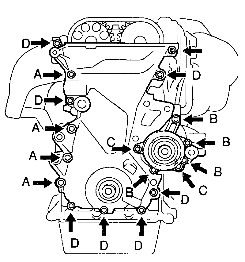
e. Install the timing chain cover, O-ring and water pump with the 19 bolts. Uniformly tighten the bolts in several passes.
Torque:
A: 21 Nm (214 kgf-cm, 15 ft. lbs.)
B: 11 Nm (113 kgf-cm, 8 ft. lbs.)
C: 9.0 Nm (92 kgf-cm, 80 inch lbs.)
D: 9.0 Nm (92 kgf-cm, 80 inch lbs.)
NOTICE:
- Pay attention not to wrap the chain and slipper over the chain cover seal line.
- After install the chain cover, must install the mounting bracket and water pump within 15 minutes.
f. Using a torx wrench socket (E8), install the stud bolt.
Torque: 9.3 Nm (95 kgf-cm, 82 inch lbs.)
9. 1ZZ-FE: INSTALL RH ENGINE MOUNTING BRACKET
a. Apply seal packing to threads of the mounting bolt.
Seal packing: Part No. 08826-00080 or equivalent
HINT: Do not apply seal packing to 2 or 3 threads of the bolt end.
b. Install the mounting bracket with the 3 bolts.
Torque: 47 Nm (479 kgf-cm, 35 ft. lbs.)
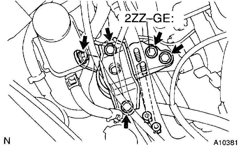
10. 2ZZ-GE: INSTALL RH ENGINE MOUNTING BRACKET
Install the mounting bracket with the 4 bolts.
Torque: 49 Nm (500 kgf-cm, 36 ft. lbs.)
11. INSTALL DRIVE BELT TENSIONER
a. Check the appearance before installing the drive belt tensioner.
If in case of having the oil leakage, crack, and etc., replace the drive belt tensioner.
b. Install the drive belt tensioner.
Torque:
Bolt
1ZZ-FE 69 Nm (704 kgf-cm, 51 ft. lbs.)
2ZZ-E 100 Nm (1,020 kgf-cm, 74 ft. lbs.)
Nut 29 Nm (296 kgf-cm, 21 ft. lbs.)
c. Hook the tool on the hexagonal portion of the drive belt tensioner bracket and operate drive belt tensioner 3 times with full stroke.
HINT: Take 3 seconds or more for 1 full stroke.
12. INSTALL CRANKSHAFT POSITION SENSOR
Torque: 9.0 Nm (92 kgf-cm, 80 inch lbs.)
13. INSTALL CRANKSHAFT PULLEY
a. Clean the crankshaft pulley inside.
b. Align the pulley set key with the key groove of the pulley, and slide on the pulley.
c. Using SST and 2 nuts (width: 10 mm (0.25 inch), install the pulley bolt.
SST 09213-70010, 09330-00021
Torque:
1ZZ-FE 138 Nm (1,409 kgf-cm, 102 ft. lbs.)
2ZZ-GE 120 Nm (1,200 kgf-cm, 87 ft. lbs.)
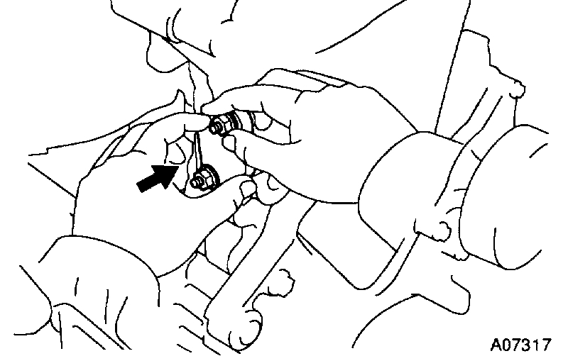
14. INSTALL CHAIN TENSIONER
a. Check the chain tensioner.
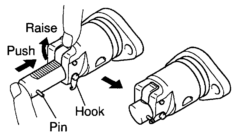
b. Release the ratchet pawl, fully push in the plunger and apply the hook to the pin so that the plunger cannot spring out.
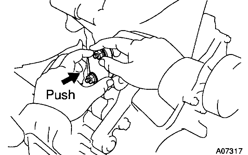
c. Insert the O-ring with your hand until it reaches to the chamfering position and install nut temporally. Then, by tightening the nut, insert the chain tensioner to the installation position.
HINT:
- In the case that the hook is released while pushing in, apply the hook again and push the tensioner in.
- Pay attention not to catch the O-ring as it is built in the chain tensioner previously.
d. Tighten the 2 nuts.
Torque: 9.0 Nm (92 kgf-cm, 80 inch lbs.)
15. SET CHAIN TENSION
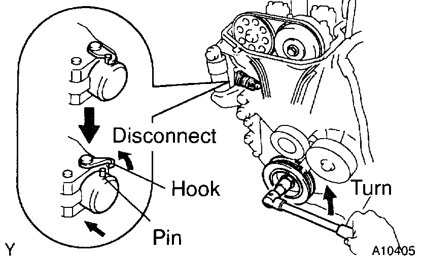
a. Turn the crankshaft counterclockwise, and disconnect the plunger knock pin from the hook.
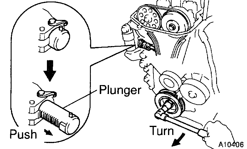
b. Turn the crankshaft clockwise, and check that the slipper is pushed by the plunger.
HINT: If the plunger does not spring out, press the slipper into the chain tensioner with a screwdriver or your finger so that the hook is released from the knock pin and the plunger springs out.
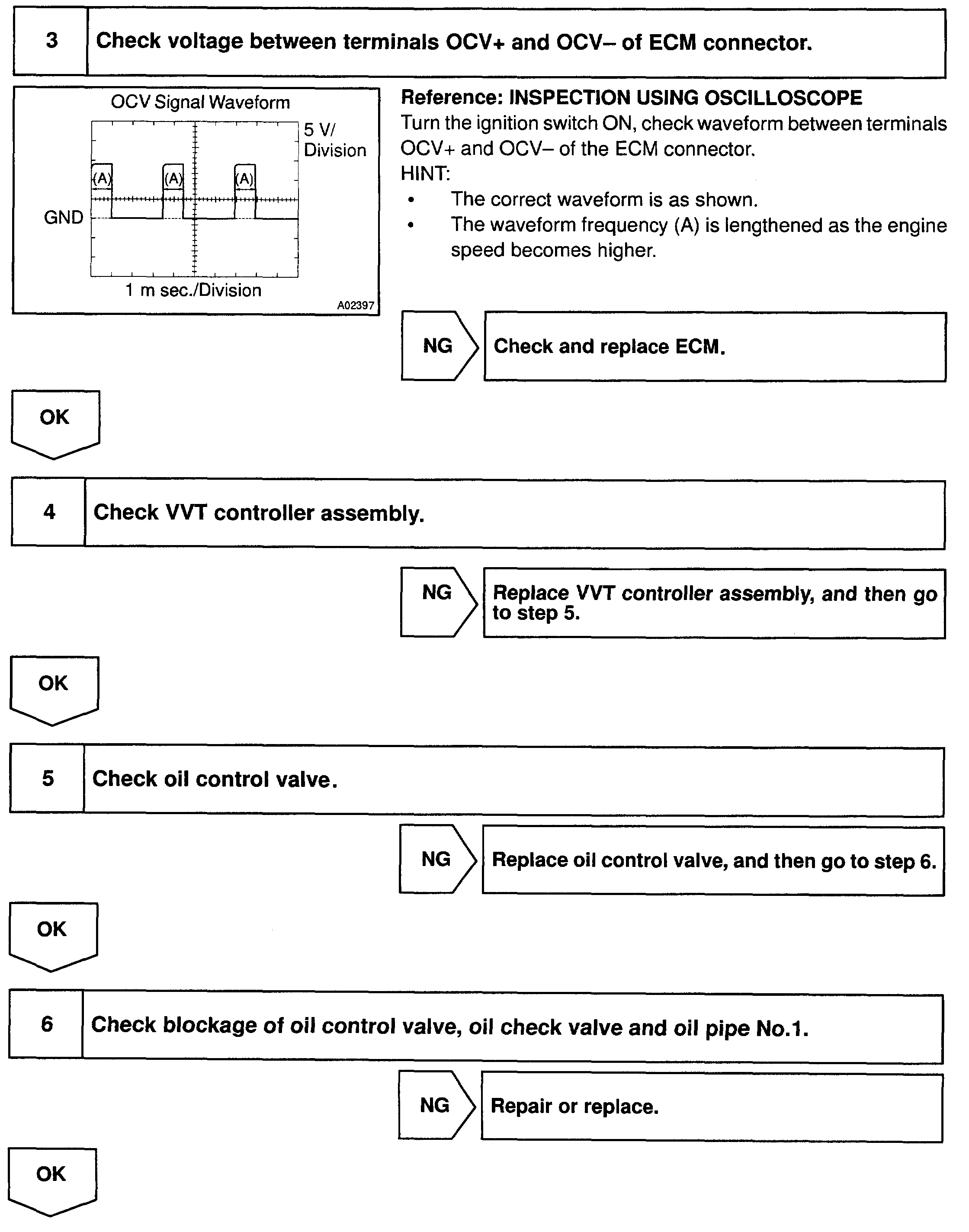
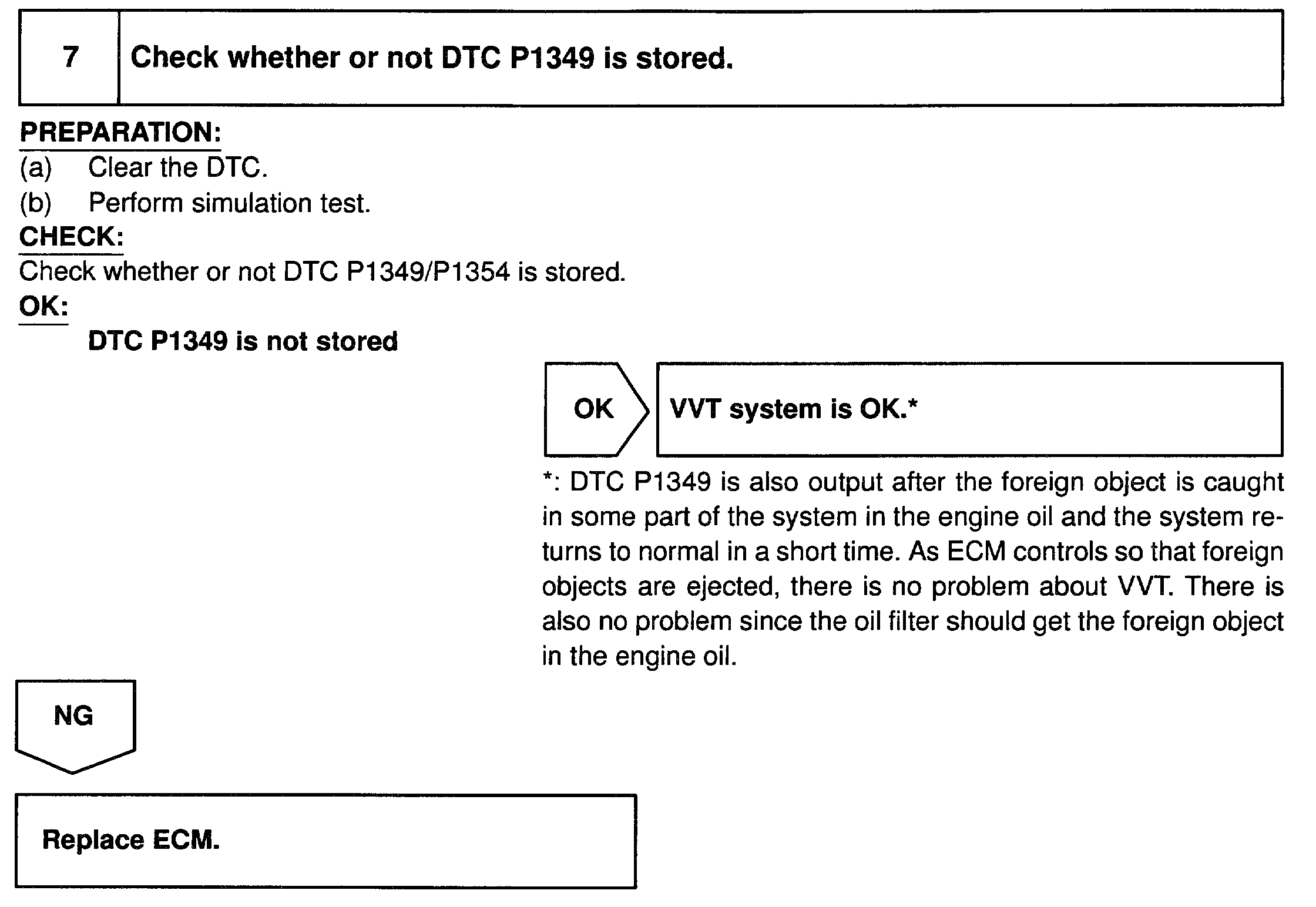
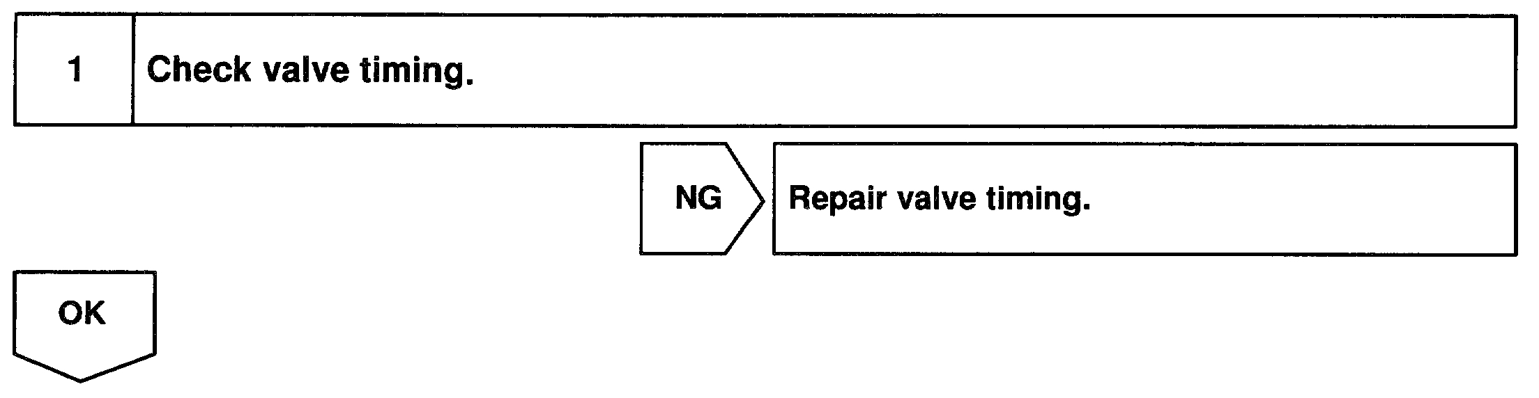
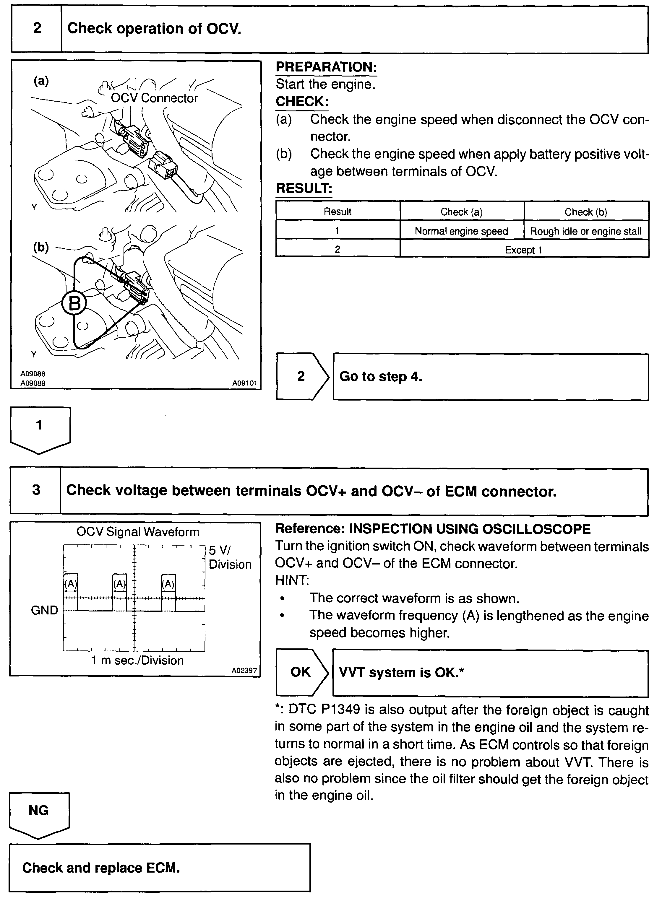
16. CHECK VALVE TIMING
a. Turn the crankshaft pulley, and align its groove with timing mark "0" of the timing chain cover.
NOTICE: Always turn the crankshaft clockwise.
b. Check that the point marks of the camshaft timing sprockets are in straight line on the timing chain cover surface as shown in the illustration.
If not, turn the crankshaft 1 revolution (360°) and align the marks.
17. 1ZZ-FE: INSTALL CYLINDER HEAD COVER
a. Remove any old packing (FIPG) material.
b. Apply seal packing to 2 locations as shown in the illustration.
Seal packing: Part No. 08826-00080 or equivalent
c. Install the gasket to the cylinder head cover.
HINT: Part must be assembled within 3 minutes of application. Otherwise the material must be remove and reapplied.
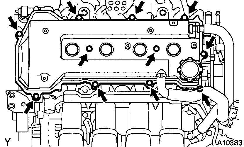
d. Install the cylinder head cover with the 9 bolts, 2 seal washers and 2 nuts.
Uniformly tighten the bolts and nuts, in the several passes, in the sequence shown.
Torque:
w/o washer 11 Nm (113 kgf-cm, 8 ft. lbs.)
w/ washer 9.0 Nm (92 kgf-cm, 80 inch lbs.)
e. Connect the 2 PCV hoses to the cylinder head cover.
f. Install the ignition coil.
18. 2ZZ-E: INSTALL CYLINDER HEAD COVER
a. Remove any old packing (FIPG) material.
HINT: When FIPG on the head cover gasket side cannot be eliminated completely, replace the gasket.
b. Apply seal packing to 2 locations as shown in the illustration.
Seal packing: Part No. 08826-00080 or equivalent
c. Install the gasket to the cylinder head cover.
HINT: Part must be assembled within 3 minutes of application. Otherwise the material must be remove and reapplied.
d. Install a new O-ring to the cylinder head cover.
e. Install the cylinder head cover and wire harness protector with three bolts. Uniformly tighten the bolts, in the several passes, in the sequence shown.
Torque: 10 Nm (100 kgf-cm, 7 ft. lbs.)
f. Connect the 2 PCV hoses to the cylinder head cover.
g. Install a new gasket and No. 1 ventilation pipe with 2 nuts and bolt.
Torque:
Nut 10 Nm (100 kgf-cm, 7 ft. lbs.)
Bolt 25 Nm (255 kgf-cm, 18 ft. lbs.)
h. Connect the No. 3 ventilation hose to the No. 1 ventilation pipe.
i. Install the ignition coil.
19. INSTALL RH ENGINE MOUNTING INSULATOR
a. 1ZZ-FE: Install the RH engine mounting insulator with the 4 bolts and 2 nuts.
Torque: 52 Nm (530 kgf-cm, 38 ft. lbs.)
b. 2ZZ-GE: Install the RH engine mounting insulator with the 5 bolts and 2 nuts.
Torque: 52 Nm (530 kgf-cm, 38 ft. lbs.)
20. INSTALL PS PUMP
a. Install the PS pump with the 2 through bolts and nuts.
Torque: 36 Nm (370 kgf-cm, 27 ft. lbs.)
b. Install the PS pump pulley with the pulley nut.
c. Connect the PS oil pressure switch connector.
21. INSTALL GENERATOR AND DRIVE BELT
22. INSTALL RH ENGINE UNDER COVER
23. INSTALL RH FRONT WHEEL
24. FILL WITH ENGINE COOLANT
25. INSTALL FRONT FENDER APRON SEAL AND UPPER RADIATOR SUPPORT SEAL
26. START ENGINE AND CHECK FOR COOLANT LEAKS
____________________________________
I hope this is helpful. Let me know if you have problems or other questions.
Take care,
Joe
Images (Click to enlarge)
Oct 16, 2018 at 6:22 PM