Throttle sensors

Tiny
NOTARY5745
  • MEMBER
  • 2006 JEEP GRAND CHEROKEE
  • V8
  • 4WD
  • AUTOMATIC
  • 155,000 MILES
Change throttle position sensor several times and finally put in Mooar sensor and still not correcting code. Still shows voltage surge.
Tuesday, January 11th, 2022 AT 3:11 PM

13 Replies

Tiny
CARADIODOC
  • MECHANIC
  • 33,763 POSTS
You have to list the engine size because two totally different systems were used. Also, the exact fault code number will give us the starting point in the diagnosis. There's multiple fault codes related to the throttle position sensor, and they mean very different things.

If you have the 3.7L or 4.7L engine, the TPS is a very low-failure item. Wiring and connector terminal problems are much more likely. If you have access to a scanner, that will speed up the diagnosis. If you don't, we can solve this with an inexpensive digital voltmeter.

For others researching this topic, if you need help using a voltmeter, this article will get you started:

https://www.2carpros.com/articles/how-to-use-a-voltmeter

Let me know if you have a voltmeter or scanner. You'll need to get to the TPS to take voltage readings, but to be accurate, those readings have to be taken with the connector plugged in and while the symptom or problem is occurring.
Was this
answer
helpful?
Yes
No
Tuesday, January 11th, 2022 AT 4:19 PM
Tiny
NOTARY5745
  • MEMBER
  • 5 POSTS
4.7l
Was this
answer
helpful?
Yes
No
Tuesday, January 11th, 2022 AT 4:24 PM
Tiny
CARADIODOC
  • MECHANIC
  • 33,763 POSTS
What's the fault code number and symptom? I need details to know how to diagnose the cause.
Was this
answer
helpful?
Yes
No
Tuesday, January 11th, 2022 AT 4:26 PM
Tiny
NOTARY5745
  • MEMBER
  • 5 POSTS
Code 0123.
I also had the clockwork spring checked.
Was this
answer
helpful?
Yes
No
Thursday, January 13th, 2022 AT 10:50 AM
Tiny
CARADIODOC
  • MECHANIC
  • 33,763 POSTS
P0123 - Throttle/Pedal Position Sensor/Switch A Circuit High Input

Dandy. Since you already replaced the sensor, there's only two things that can set this code. We know 5.0 volts has to be getting to the sensor on the pink / yellow wire so that circuit is okay.

A break in the ground circuit will do this, but that circuit is shared with multiple other sensors Measure the voltage on the dark blue / dark green wire by back-probing through the rubber seal around the wire. Remember, these are only accurate if the connector remains plugged in to the sensor. You should find 0.2 volts. If you find 5.0 volts, there's a break in the section with the blue bracket. If it was in any other part of that circuit, you'd have fault codes for other sensors and the engine wouldn't run

The signal circuit can be more confusing. First, if you do find a break in the dark blue / dark green ground wire, there will be 5.0 volts on the brown / orange signal wire too. Any voltage outside the standard range of 0.5 to 4.5 volts is what sets these codes, and the only way to get these voltages is by having a break in one of the circuits.

If the ground circuit does have 0.2 volts, but you find 5.0 volts on the brown / orange signal wire, there has to be a break inside the sensor, or between one pair of mating terminals in the connector. The 5.0 volts gets there through a "pull-up" resistor inside the Engine Computer. That resistor is tied internally to the regulated 5.0-volt power supply, but it is so big electrically that when the circuit is working properly, it has no effect. It's only when a defect exists that it puts the 5.0 volts onto the signal wire to force the defective condition to be detected.

Now for the confusing part. Once you understand how these sensors work, the diagnosis can be sped up by taking just one voltage reading. That's on the signal wire as you work the throttle from "idle" to "wide-open-throttle" by hand. You should see a smooth change from 0.5 to 4.5 volts. The only way to get that proper operation is if the 5.0-volt feed and ground circuits are okay. No need to test them. Those voltages are for training purposes. In actual practice, you might see 0.72 to 4.2 volts, for example. The exact values aren't important and will be different for every throttle position sensor you install. The point is it must never reach 0.0 or 5.0 volts.

What we're looking for here is if you find that proper voltage sweep at the sensor, but the computer is seeing 5.0 volts all the time. The only way to know that is to see it on a scanner while viewing live data. The same voltage has to be seen at both brown arrows in this diagram. The only way they can be different is if there's a break between those two points. Here again, with a break in the brown / orange wire, the pull-up resistor will put 5.0 volts on that signal terminal inside the computer to force the defect to be detected.

Tell me what you find with these voltage readings. Be aware too, especially with spread connector terminals, these defects can be intermittent. A momentary break when you bounce over a bumpy road is enough to set the fault code, but the circuit could go back to proper operation. This is where fault codes can seem to have an elusive cause. The best way to work on that type of problem is to take a scanner along on a test-drive.
Was this
answer
helpful?
Yes
No
Thursday, January 13th, 2022 AT 6:16 PM
Tiny
KASEKENNY
  • MECHANIC
  • 18,907 POSTS
Just to add to this as there was a comment added that what it means if the voltage is.02 and not.2 as stated above.

This voltage is not much different between the two readings. They both mean that the circuit is intact, and the ground is okay.

So, if you have.02 volts on the circuit were shown above, you are after the load so what you are getting is all that is needed to complete the circuit.

The basic circuit operates by the voltage that is supplied is used by the load with the only voltage remaining on the ground side, is that needed to return the current to ground.

Please let us know if more info is needed. Thanks
Was this
answer
helpful?
Yes
No
+1
Thursday, January 20th, 2022 AT 5:00 PM
Tiny
NOTARY5745
  • MEMBER
  • 5 POSTS
Okay, now it is revving up and then stalling. If he disconnects the throttle sensor it runs fine.
Was this
answer
helpful?
Yes
No
Thursday, January 20th, 2022 AT 5:18 PM
Tiny
NOTARY5745
  • MEMBER
  • 5 POSTS
The voltage that you said should be.2 is.02 any suggestions? Now he ran a ground jumper. A

So, he said the ground was fine unfortunately now for some reason it is revving up and then stalls. If he unplugs the Throttle sensor it runs correctly. Any ideas?
Was this
answer
helpful?
Yes
No
Thursday, January 20th, 2022 AT 5:48 PM
Tiny
KASEKENNY
  • MECHANIC
  • 18,907 POSTS
Just reading through this info, I want to be sure we are providing the testing from the manual.

It sounds like your PCM is the issue, but we need to run through this specific testing and confirm this.

Basically, if unplugging the TPS causes the issue to stop causes then the issue is in the 5-volt supply being sent to the TPS, the wiring, or the TPS.

If the TPS has been replaced and it is still acting up, there is a chance that this is wiring but that is less likely. However, this testing will prove that out.

I am sure you will find the answer by running through this testing so run through this and let me know if you have questions on any portion of this.

Thanks
Was this
answer
helpful?
Yes
No
Thursday, January 20th, 2022 AT 6:14 PM
Tiny
CARADIODOC
  • MECHANIC
  • 33,763 POSTS
.02 volts is correct. Basically, this is a ground circuit where you would expect to find 0.00 volts. The difference here is many sensors have their ground wires tied together, then that circuit goes to ground through the Engine Computer. That's so the computer can monitor that circuit. The.02 volts is what is "dropped" across the monitoring circuit. Normally voltages that low we would call "0" volts, but every once in a while, someone is sharp enough to see that little voltage and question it.

I still want to know the exact range of signal voltage you see on the brown / orange wire. That will instantly tell us if the sensor is working correctly.

Any time you unplug a sensor while the engine is running, the computer will see that, then besides setting the fault code, it will do two things. First, it will "inject" an approximate value it as calculated based on all the other sensor readings and engine operating conditions and use that to run the engine. Performance won't be perfect, but it will be good enough that you can drive the vehicle. Second, the computer is constantly running hundreds of tests on all of its circuits while you're driving. Besides the electrical tests such as those I'm having you do, it also compares a lot of things to determine when something is wrong. For example, when the engine has been off for at least six hours, it knows the intake air temperature sensor and the coolant temperature sensor had better be reading the same temperature. Even though the wiring might be okay, if those readings are different, there are strategies to figure out which one is wrong.

In this example, if you were to disconnect the intake air temperature sensor, the resulting fault code would force some of the performance tests on the coolant temperature sensor to be suspended. Some defects would go undetected. It's not until you reconnect the intake air temperature sensor that all the suspended tests resume.

As a side note, this is a big cause of taking your vehicle in for repair for the Check Engine light being on, and after repairs are completed and you're driving away, the light comes back on again. You're frustrated because you incorrectly assume the car wasn't repaired correctly. The mechanic is frustrated because he knows you're angry, and because he had no way of knowing another problem existed. Also, he has to start the diagnosis all over again, then tell you more parts are needed. We really don't like having to do that. This chain of events is more likely to happen when the first problem is ignored for a long time, as in many months. That gives more time for a second, different problem to develop.

When you disconnect the throttle position sensor and something changes, that proves that sensor is working. The only thing you can possibly have now is a defective condition, so if the engine runs better, it's because of something else the computer is ignoring.

Of all the sensors on the engine, the throttle position sensor has the least say in fuel metering calculations. The sensor that has the most influence on Chrysler engines is the MAP sensor. On most other car brands, it's the mass air flow sensor. Next are the temperature sensors. The throttle position sensor tells the computer throttle position, when it's at idle, when it's at wide-open-throttle, the direction of throttle change, and the rate of change. If you were able to manipulate the throttle position sensor by hand, at most, the engine would only speed up a couple hundred rpm above idle, and it won't cause stalling.

Engine speed increasing on its own is usually due to some type of vacuum leak. Idle speed is controlled by a motorized valve that opens an air passage around the throttle blade. That valve can be set to any of 256 "steps". For a properly running engine that's warmed up, step "32" is typical. With a small vacuum leak, the computer will close the valve a little more, let's say to step "10". The engine may run okay, until you do something to block that vacuum leak, then step 10 is too low and the engine may stall if the computer can't reopen that valve fast enough. All engines rock back and forth on rubber engine mounts. That small movement can be enough to momentarily close up a leaking vacuum hose.

I have a '94 Voyager that the previous owner had in the shop three times over many years for a very intermittent failure to up-shift. Happened to me twice in three years, then it turned into a slightly high idle speed for a couple of days, culminating in a failure to start and run. No experts or specialists could solve this until it was acting up while I had my scanner connected. At that point it took less than two minutes to see the cause of the problem, then another few minutes to overcome my disbelief in what I found. The solution took five minutes. The point of this story is no one could figure out what was happening without the scanner to show live data. I still want to know what you have for throttle position sensor signal voltage, but we're throwing darts in a dark room by not having the scanner. If you don't have access to one, you may be ahead in dollars and time by enlisting the help of a mechanic.

Most scanners also have a "record" feature that lets you record a few seconds of sensor data that can be played back slowly, later, to see what changed when the problem occurred. That is extremely useful when trying to figure out why an engine stalled.

Let me know what you find for that signal voltage from idle to wide-open-throttle.
Was this
answer
helpful?
Yes
No
Friday, January 21st, 2022 AT 7:00 PM
Tiny
NOTARY5745
  • MEMBER
  • 5 POSTS
Hello, my mechanic has tried everything with the wiring and all of the voltage is where is should be except for when it is idling, and he also replaced the computer because the idling was at 5 and everything else was showing correct voltage. Unfortunately, it is still showing 4 when it is idling. Do you have any suggestions? I would greatly appreciate it.
Was this
answer
helpful?
Yes
No
Thursday, February 3rd, 2022 AT 9:42 AM
Tiny
CARADIODOC
  • MECHANIC
  • 33,763 POSTS
You still haven't posted the voltage readings I need. For the "4" and "5" you listed, are those engine speed as in 400 rpm, or 4.0 volts for the throttle position sensor reading?

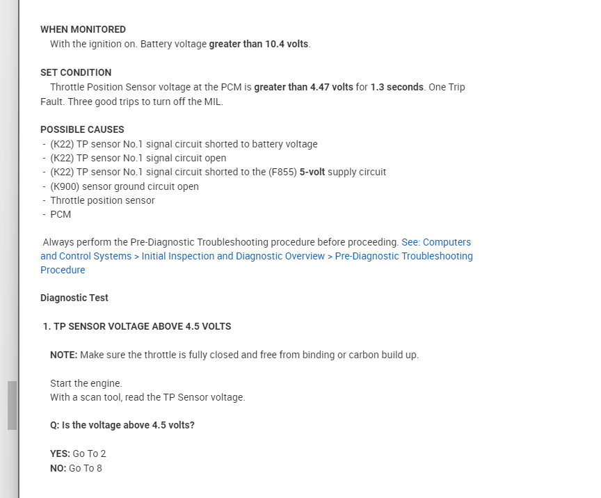
Your mechanic would have used a scanner, so we know we have access to the information we need. All of the voltage tests I listed can be boiled down to just one thing on the scanner. That's the "TPS Signal Voltage". It must vary between roughly 0.5 to 4.5 volts from idle to wide-open-throttle. If that is what's seen on the scanner, that is what the computer is seeing, and that range can only occur if every other part of the circuit is working. At that point no other tests are needed or will provide any useful information.

The fault code(s) should be erased, then observe if and when it sets again. If it sets again immediately, there is a defect that is occurring right now and should show up as a wrong TPS signal voltage on the scanner. If the code comes back later, typically during a test-drive, we're looking for an intermittent problem. This is where spread or corroded connector terminals become the best suspect. Wiggling wiring harnesses might make the defect show up. Watching the reading during the test-drive can also help by showing what it takes to make the defect occur.

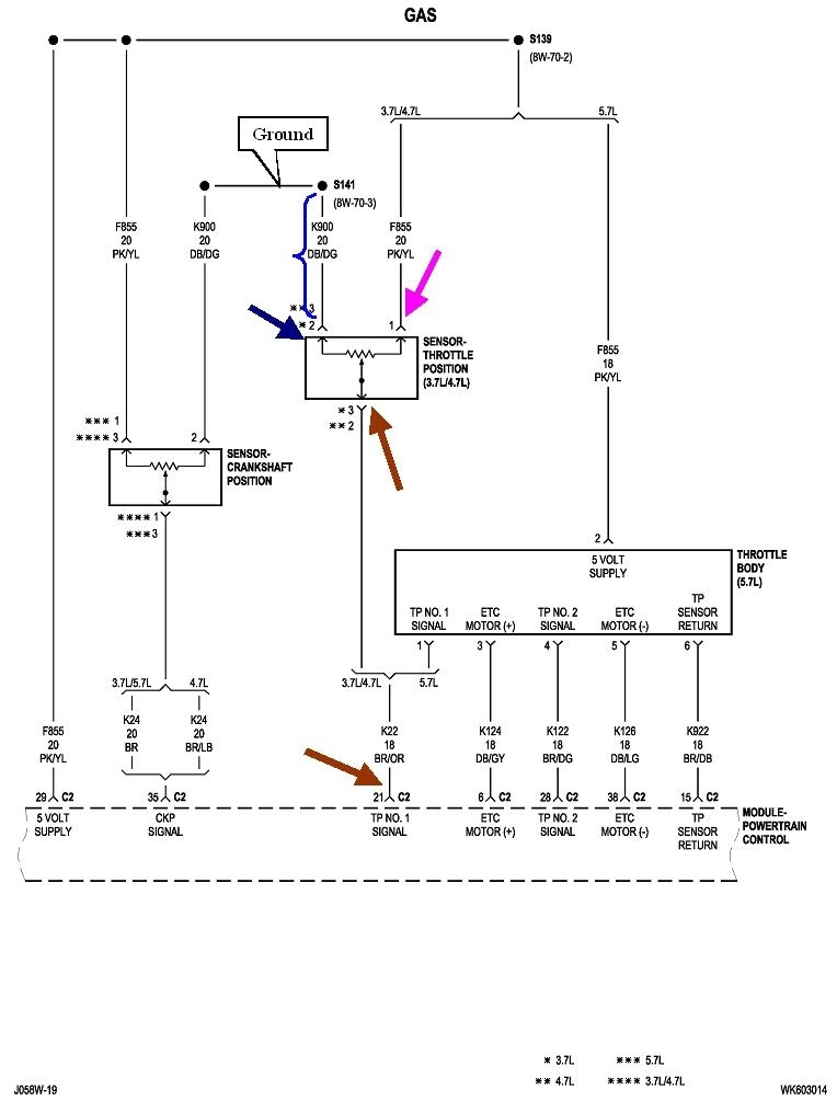
I'm surprised that I failed to make two comments earlier. I apologize for that. Thought I would have done that before. The first is I have to correct the ground voltage I listed as ".02 volts". In fact, I was corrected earlier and overlooked it. You will see 0.2 volts, (two tenths of a volt). In this circuit that is significantly different than 0.00 volts as would be expected, on a ground wire, or.02 volts.

The second has to do with "minimum throttle". This has to do with idle speed that's too low, and to my knowledge, it only applies to Chrysler products. Any time the battery is disconnected or run dead, and fifty percent of the time when you replace the throttle position sensor, minimum throttle has to be relearned. Fuel trim data and all other sensor personalities are relearned right away without you even noticing. Minimum throttle is the one big exception. That requires a very specific set of conditions so the computer knows your foot is off the accelerator pedal.

To meet those conditions, drive at highway speed with the engine warmed up, then coast for at least seven seconds without touching the pedals.

Until that is done, idle speed will be too low. The engine may not start unless the accelerator pedal is held down 1/4". It will not give the nice "idle flare-up" to 1500 rpm at start-up, and it will tend to stall at stop signs.

Remember I mentioned the proper range for the TPS signal voltage is 0.5 to 4.5 volts, but that is for training purposes. In actual practice those values are approximate and will be different for every sensor. When minimum throttle is learned, the computer puts into memory the signal voltage it sees from the TPS at that instant. From then on, any time it sees that same voltage, it knows it has to be in control of idle speed. If anything happens after that to make that voltage lower, it immediately puts that new value into memory instead. That's what happens half the time when you install a new throttle position sensor. However, if you install one with a slightly higher voltage at idle, the computer will think you're holding the accelerator pedal down, so it leaves idle speed up to you. Eventually you're going to be driving and you'll meet the conditions for minimum throttle to be learned again for the new sensor, then any symptoms will "magically" disappear.

With the scanner, your mechanic had the perfect opportunity to see why engine speed was too low. That goes back to the idle "steps" I started to describe. I got as far as saying step "32" was a typical value you could find, out of the 256 total steps for a properly-running engine. If the engine is cold, it will be a little higher. Same if there's a higher load on the engine, such as when running the AC compressor or when shifting into gear. If anything slows the engine down, the computer will raise the idle speed motor / valve to a higher step in an attempt to get idle speed back up to where it should be.

There's three things we can learn from looking at the idle step number on the scanner. The scanner will also list the actual idle speed and the "desired idle speed". If those two are the same, the computer has achieved the results it is after. When they're different, the step number tells us what type of problem to look for. For example, if idle speed is too high, the step number will be lower than normal, say step 15. That shows the computer is trying to lower idle speed, but without success. A vacuum leak is the common suspect. If the idle step number is higher than normal but actual idle speed is too low, the computer wants idle speed to be higher but can't get it there. Similarly, if idle speed appears to be okay, but the step number is unusually high, the computer has achieved the idle speed it wants but it's overcoming something to do that. A common cause is a spark-related misfire. One misfiring cylinder will lower engine speed, then increasing the step number will make the other cylinders work harder to get idle speed back up to where it should be. For a single-cylinder misfire, step "50" is about what you'd expect to see.

The most overlooked clue is when the idle step number is listed as "0". That only occurs when minimum throttle hasn't been relearned. Then, a test-drive is in order to perform that relearn before wasting time trying to find other causes of low idle speed, (that don't exist). Step "0" proves the computer is not trying to control idle speed, so you can expect speed to be too low.
Was this
answer
helpful?
Yes
No
Thursday, February 3rd, 2022 AT 1:19 PM

Please login or register to post a reply.

Sponsored links