New features are coming out all the time with aftermarket radios. I'm not familiar with your radio model, so I'll tell you as much as I know.
First of all, manufacturers of aftermarket radios rarely build a model that will plug right into one specific car or truck model because their market would be too small. Instead, they build a one-size-fits-many so it can be used in multiple applications. That's why we have to buy installation kits with face plates specific to what we're putting it into. The same thing applies to computer circuits. Starting with all '96 car and truck models sold in the U.S, they all use the "on-board diagnostics, version 2, (OBD2), emissions system which includes a lot of standardized computer language. Before that, every manufacturer had their own proprietary system, and no remote radio controls. The OBD2 system standardized the computer language used for engine controls and emissions systems, but the manufacturers were still free to use their own language for other systems. Chrysler used three computer systems on most car models. That would include a 2001 truck.
The next generation of computer systems was the "CAN Buss" system. That's "controller area network". This turns every head light switch, heater control switch, tail lamp housing, etc, into its own computer module, and they all talk back and forth on the data buss. I have a suspicion that is what your radio is designed for. The first Chrysler model to go to this system was the 2004 Dakota / Durango. The last models to switch to this were some 2009 Jeep models. This is a much more standardized system among car brands, so it would be fairly easy for an aftermarket radio manufacturer to design a radio that will communicate on that data buss. The only difference would be the face plate shape and size, and the mounting method.
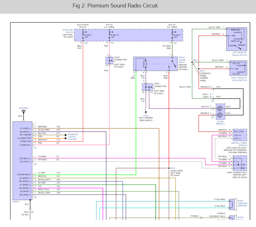
My understanding is Chrysler still uses three data busses, so any exchanging of information has to take place inside a computer that takes it in on one buss, interprets it, uses what it needs, then sends the translated data out on a different buss. This one originates in the Body Computer. Chrysler's name for that in their truck models is the "Central Timer Module", (CTM). That's shown in the upper right of the second diagram.
The Central Timer Module is supposed to protect those circuits if a wire becomes shorted to ground, but when that happens, everything that uses that data goes dead. You can go to the rear lift gate module on a minivan and ground either data buss wire, and you'll have a crank / no-start condition. The Chrysler instructors used my classroom as one of their three satellite training sites for my state, and besides attending numerous classes as a dealership employee, I got to sit in on any classes when they were using my shop. This is where I saw that demonstration with the data buss.
If your radio is not designed to work with these digital signals, it is possible it will take out the data buss. Everything should come back once the offending item is disconnected, and the ignition switch is turned off, then back on.
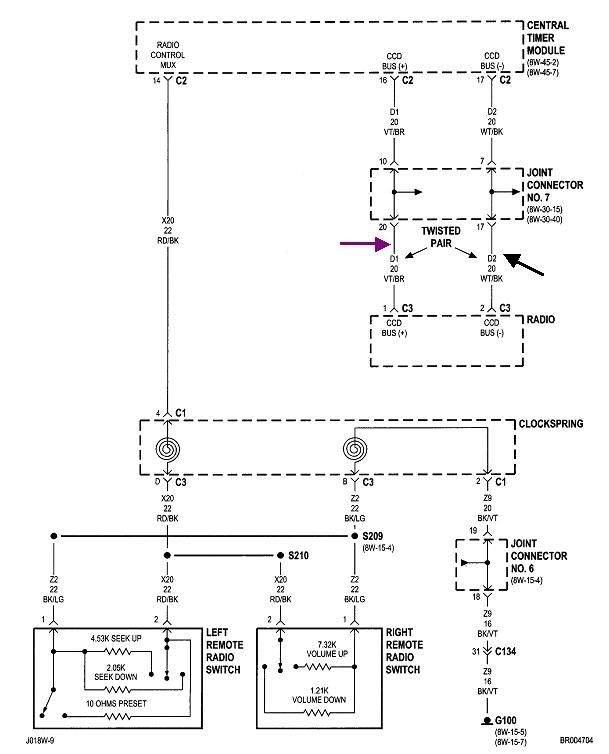
As for which wire to use, they both send the same signals, but mirror images of each other. Both have six volts on them put there by the Central Timer Module. The signal on the "CCD+" wire is a digital square wave that goes only about 0.2 volt higher. To say that a different way, the signal pulses between 6.0 and 6.2 volts. That tiny voltage makes it susceptible to stray electromagnetic interference from all the adjacent wires, especially those that run parallel to each other. That's why you'll see them listed on the diagrams as a "twisted pair", and that's how you'll find them in the truck. Any interference that generates a voltage spike in one wire will do so equally in the other wire. The net difference is zero, and those signals will cancel out.
The "CCD-" wire has an identical signal, but upside-down compared to the CCD+ wire. It's signal pulses between 6.0 and 5.8 volts. By having two twin signals, each computer on that data buss can be sure it's seeing the correct signal. Minor spikes on one wire can be ignored.
Think of the data buss as the two wings on a bird. He won't get far with just one wing. You're asking which wire to connect your radio to. To use a true data buss to communicate with the steering wheel switches, through the Central Timer Module, your radio needs both wires too. If it only requires one wire, my first concern is you won't have that twisted pair. Keep that wire as short as possible because it is going to act like an antenna for stray voltage spikes. The heater control, fan motor, even the dash lights could inject signals onto the data buss and confuse the other computers. The dash lights use "pulse-width dimming" meaning they are pulsed on and off 400 times per second, and the ratio of on-time to off-time is varied to adjust the brightness. That's 12 volts that is switched rapidly on and off, and that creates voltage spikes. That's highly-desirable in an ignition coil, but it must be avoided in other applications.
If I had to make an educated guess, when using just one data buss wire, I'd choose the "CCD+" wire. If that works, I would expect to see something to that effect in the radio's owner's manual.
Please remember, the digital signals on a data buss are totally different from on / off switch settings, and from the older resistive steering wheel controls on older vehicles. Even in your truck, if you look at the lower left in the second diagram, you'll see the steering wheel switches, and each one switches in a different resistance value. Each switch puts a different voltage on that circuit. On older vehicles, it was the radio that interpreted those voltages to know which function was being selected. Now, with the Central Timer Module, that is what is interpreting those different voltages, then it sends a digital signal out on the data buss for all the computers to see. In this case only the radio cares about that data and uses it. Steering wheel control inputs are simply ignored by all the other computers.
With the earliest voltage multiplexing steering wheel controls, GM's radios could not interpret the switch voltages on a Ford product, and a Ford radio couldn't communicate with a Chrysler vehicle. So which system should an aftermarket radio manufacturer build his radio to work in? The answer was they built an adapter module to take in the data for each different vehicle, and all of them translated the data into the one language the radio understood. That's why you need some kind of module to listen to your steering wheel controls, and tell it to the radio. As I mentioned, I'm not familiar with what the aftermarket industry is doing, but I would be surprised if they had one radio model that will work in any vehicle without some kind of module between the data buss and the radio.
Images (Click to make bigger)
Friday, April 5th, 2019 AT 6:09 PM