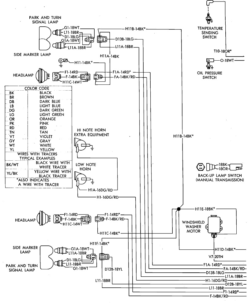
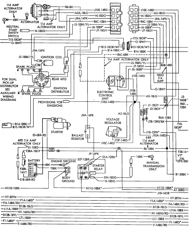
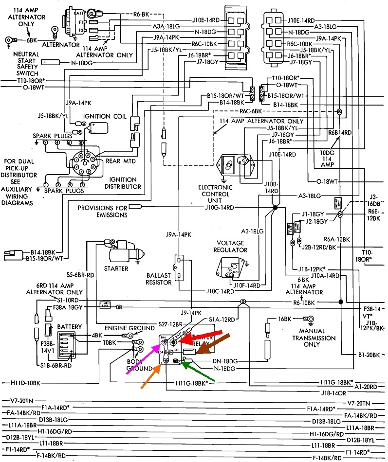
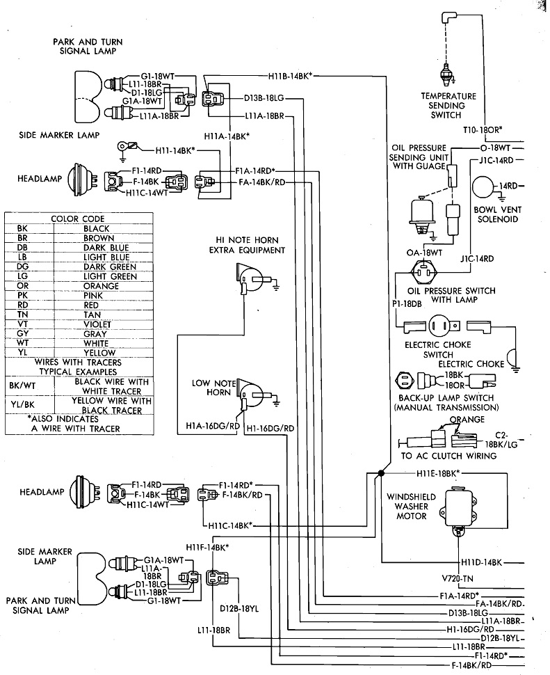
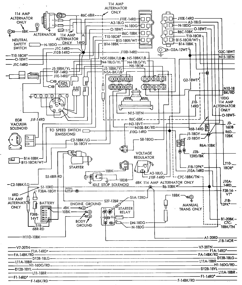
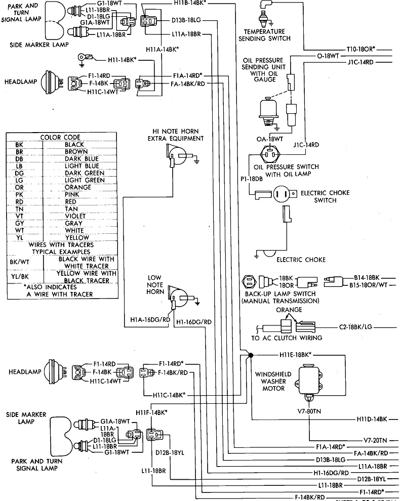
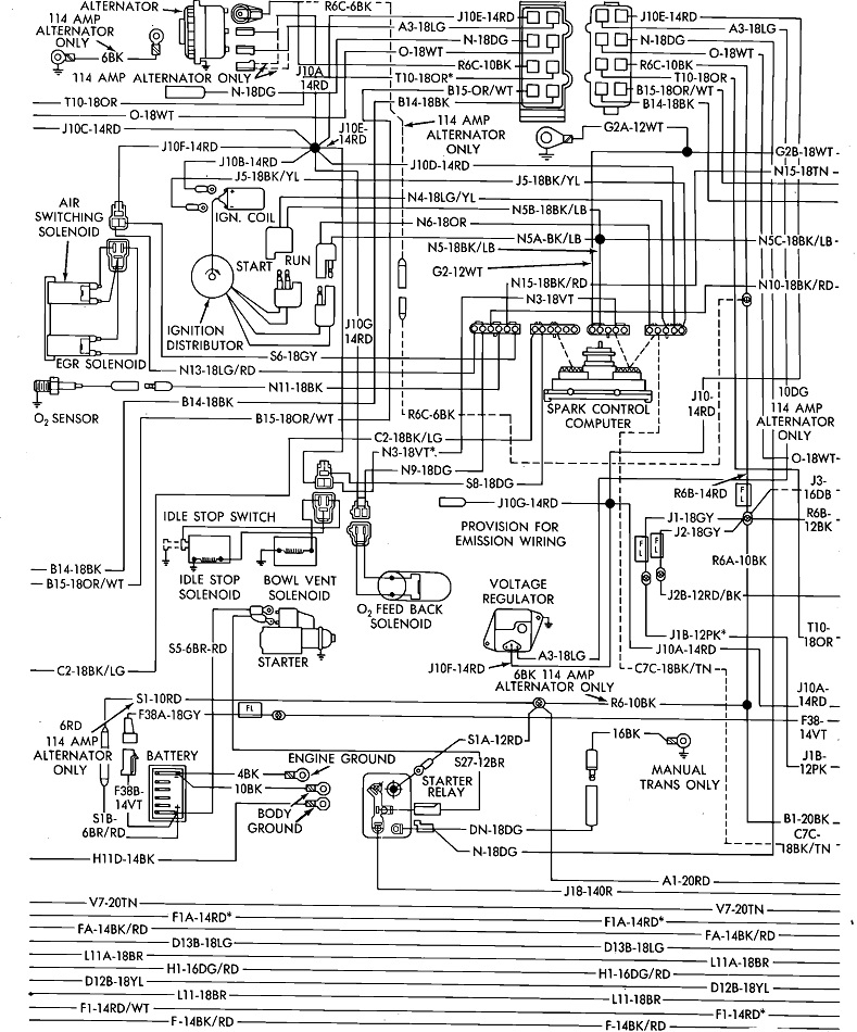
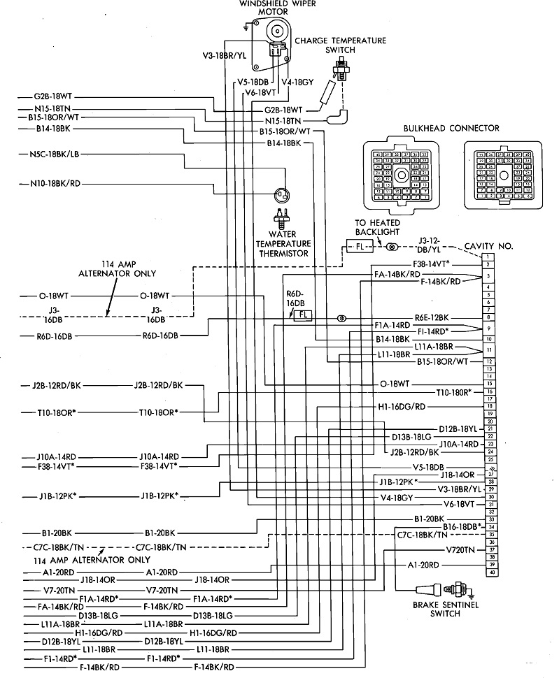
First, these three diagrams are for everything under the hood. The starter relay is in the second one, near the bottom. The fourth diagram is the second one, but I added some arrows at the starter relay.
Diagrams 5, 6, and 7 are for the ignition system without the feedback carburetor. The last three are with the feedback carburetor. As best as I can remember, you can identify the feedback carburetor by the two dark green wires going to a small solenoid on the top of the carburetor near its front.
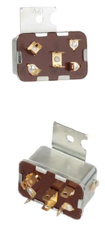
I included all of these diagrams in case you need them later. I can't find a drawing to show the starter relay's location, so you'll have to go by the wire colors. The last image shows what one version of the relay looks like. There are other similar versions with more terminals for when the distributor has two pickup coils instead of one. Those weren't very common. The second coil is switched for easier starting. It is slightly retarded compared to the main coil. The rather large Engine Computer is mounted right behind the hood, just left of center. I think the starter relay is in that area too.
To test the starter system, it can be broken down into three stages; the low-current circuit, the medium-current circuit, and the high-current circuit. I'll list the steps in order. At the relay, the first test is to check for 12 volts on the orange wire when the ignition switch is in the "crank" position. That wire comes from the ignition switch and is the start of the low-current circuit. Next, switch your meter to the lowest Ohms scale and do a continuity check on the dark green wire to ground. That's the other half of the low-current circuit. It goes through the neutral safety switch. There's another connector shown in that circuit. That's a good place to look for corroded terminals. If you find an open circuit, shift to neutral, then check it again. There's three wires on the neutral safety switch, all in a line. The two outer terminals make a connection to turn on the back-up lights. The center one connects to ground when in "park" or "neutral". That switch is screwed into the left rear corner of the transmission, right above the pan's flange. If you replace it, there's a thin aluminum gasket that goes with it that should be replaced too.
Now that I shared that wondrous part of the story, a better test is to listen or feel for that relay to click when you turn the ignition switch to "crank". If it does, that entire low-current circuit is working. If it is working, . . .
the next step is to verify there is 12 volts on the fat red wire. That comes right from the battery positive terminal and is the start of the medium-current circuit. This can be in the order of 10 to 15 amps, so the contacts in the relay will be quite substantial. If you have that 12 volts, next do a continuity test on the fat brown wire, to ground. That goes to the starter solenoid, through its two coils, then to ground. Those coils have very low resistance, so that circuit will measure like it is shorted to ground. We can discuss that solenoid more, later, if necessary. If you find good continuity, and you find 12 volts appears on that brown wire at the solenoid, but it doesn't engage, one of the two coils can be open. That is a very uncommon failure, but it has happened before. The strength of both coils is needed to get it to engage, then one is switched off internally, and the other one is strong enough to hold it engaged by itself.
Most often you will have found a problem with one of those four circuits by now. If they are working, the solenoid will engage with a rather loud, single clunk. Then, a contact disc inside the solenoid turns on the high-current circuit. That's the two battery cables, the battery, and the starter motor. On Chrysler starters, the high-current circuit can draw around 200 amps to get up and running, then it will drop to around 150 amps to keep running. GM and Ford starters of that era were not gear reduction units, so they drew closer to 300 amps to get spinning.
One of the two things I used to run into years ago with my own vehicles was the contact disc in the solenoid would become badly pitted and burned away. The head of the copper stud the battery cable is bolted to is one of the contacts. That head can burn away, and it is rather easy to replace. The second contact is not easy to replace, but it never seems to burn away. By removing a snap ring, that copper disc can be reversed to get double the life out of it.
The second problem caused a slow or dragging starter, but it did try to crank. That was due to a dragging armature caused by a badly worn bushing in the rear cover. The poor man's trick to solve that was to remove the two long bolts while holding the pieces together, rotating the cover 180 degrees, then reinstalling the bolts. The torque of trying to turn the engine forces the armature to one side where all the bushing wear takes place. By rotating the cover, you get twice the life out of that bushing.
By the way, if you remember the days of breaker points and a ballast resistor, that resistor needed to be bypassed, or shorted out, to increase spark voltage for easier starting. Ford and GM did that with a special contact and terminal on their starter solenoids. Chrysler did that with an extra terminal on the ignition switch. On your van they did it with an extra terminal on the starter relay. That's the pink wire I haven't mentioned yet. That one isn't involved with failure-to-crank problems.
Let me know how far this gets you.
Images (Click to enlarge)
May 30, 2025 at 2:32 PM