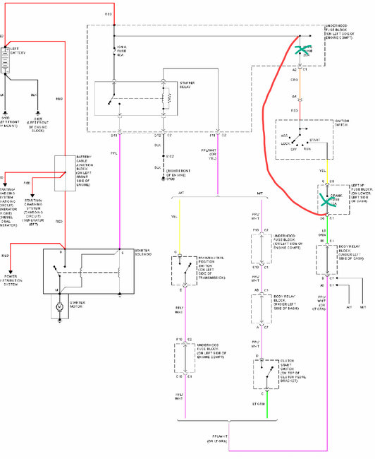
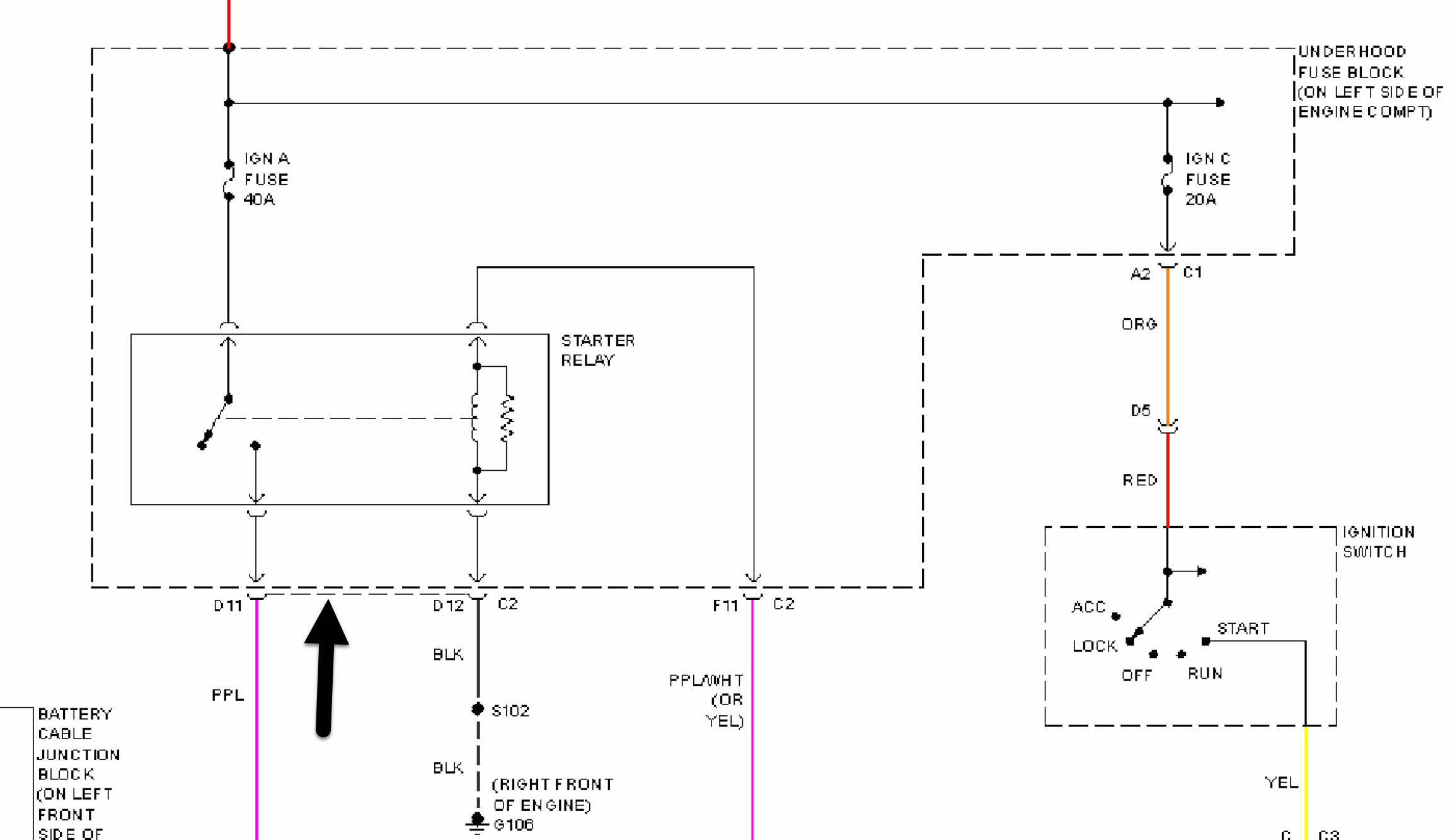
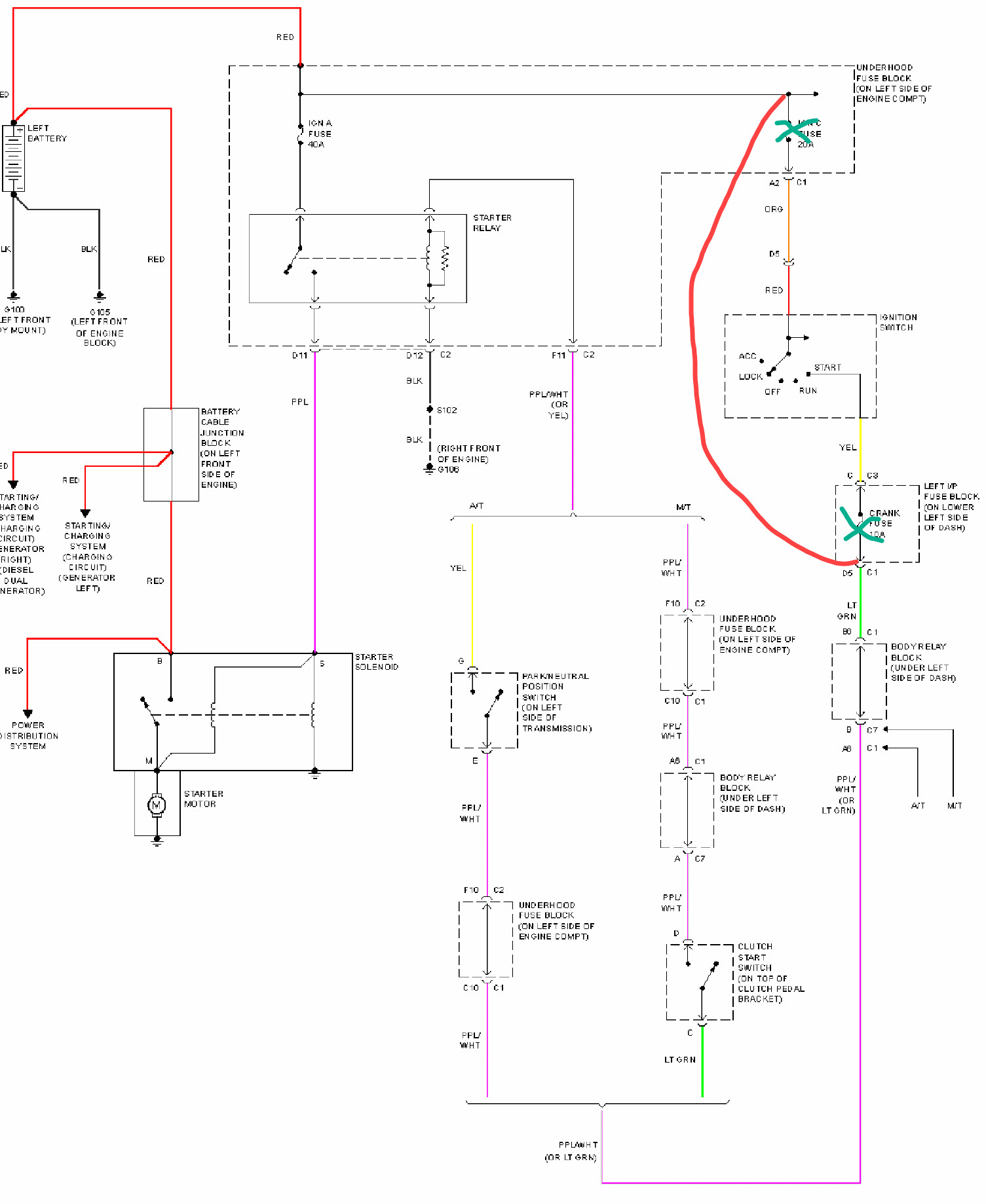
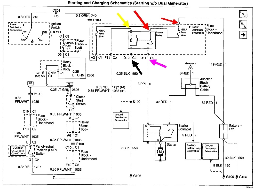
The dashed line means those two wires are in the same connector, "C2".
You're about five steps ahead in the diagnosis. Starter systems can be broken down into four parts, each with a corresponding terminal in the starter relay's socket. One of those, the red "Ign A" wire will have 12 volts all the time. You don't have to know which wire. Just look for one wire with 12 volts. Next, of the other three, one should have 12 volts only when a helper turns the ignition switch to "crank".
For the last two, we're looking for ground circuits, so if you're using a simple test light, move its ground wire to the battery's positive post. It will light up now when you touch the probe to a grounded circuit. You already found the black one. That's the ground for the relay's coil. Now there's just one remaining terminal. It must also read continuity to ground, but in this case it goes through the starter solenoid, then to ground, and through the starter motor, then to ground. Both of them have extremely low resistance, so those circuits will appear to be grounded.
Your neutral safety switch and its circuit have to be okay. If we start at the beginning, everything between the two red arrows has to be okay, otherwise the 40-amp fuse would blow as soon as you installed a new one. In fact, it doesn't blow until the relay switches on.
Next, everything up to the yellow arrow has to be okay. That's the main part of the circuit that powers the relay's coil. Since the relay is switching on, the neutral safety switch and its circuit are working. This is where you'd see 12 volts when the helper turns the ignition switch to "crank". The ground circuit, (black arrow), has to be okay too. We know that because the relay is switching on.
That leaves the purple wire going to the starter solenoid. 12 volts gets switched onto it when the relay activates. That current comes through the 40-ap fuse that's blowing. Either that wire has rubbed through and is touching the engine or the solenoid coil is shorted. Those solenoids typically draw between 10 and 15 amps; sometimes as high as 20 amps. That's because resistance is so low, in the order of one ohm or less. By comparison, your digital voltmeter's leads will have a total of as much as five ohms. It doesn't pay to try to measure the resistance because you won't be able to see a difference between normal resistance or that wire shorted to ground.
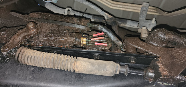
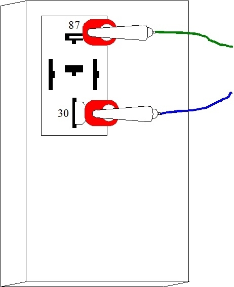
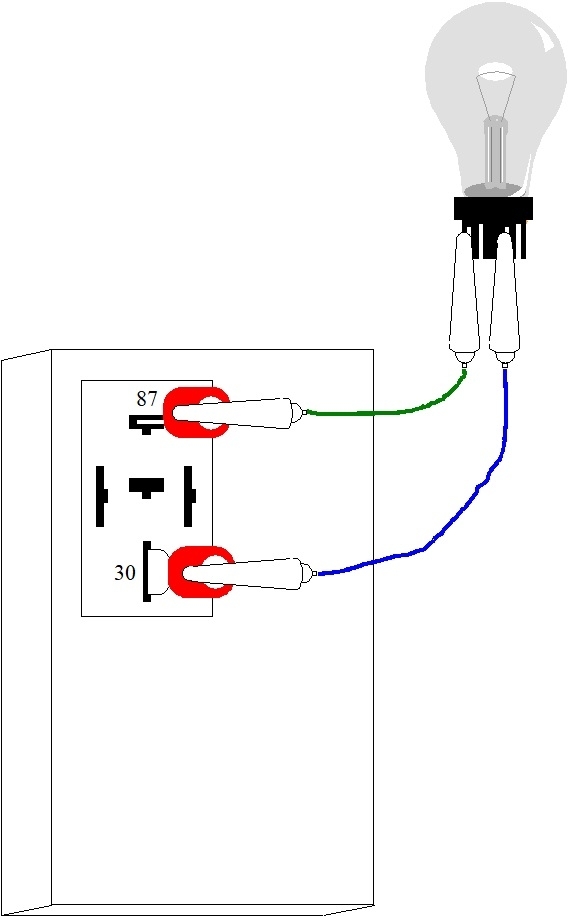
There's a better way to find this. First do a visual inspection of that purple wire, and especially the terminal on the solenoid to be it isn't touching ground. Next, remove the starter relay, then use clip leads and a light bulb to jump the red wire to the purple wire, (larger red arrow to the purple arrow). If you use a common 3157 brake light bulb on its brighter filament, that will allow one amp of current to flow. The bulb's resistance will limit current to a safe level and protect the wires. When there's a short on the purple wire, the test bulb will be full brightness and hot, so be careful to not lay it on anything that will burn or melt. Now you can wiggle or unplug things. When you do something to remove the short, the bulb will go out or in this case get dimmer.
Now that I shared that wondrous trick, the problem is as far as the bulb is concerned, there's too little difference between the solenoid's one ohm of resistance and the 0 ohms when the circuit is grounded / shorted. The change in brightness when the short is removed will be hard to see. To address that, use a larger bulb such as a head light bulb. On the "low" filament, a common 9004 bulb will pass five amps. You'll see a much larger change in brightness when you remove the short.
With the bulb in the socket, if the purple wire looks okay visually, disconnect it from the solenoid. If the bulb goes off, the solenoid is shorted or grounded internally. If the bulb remains bright, the purple wire is grounded.
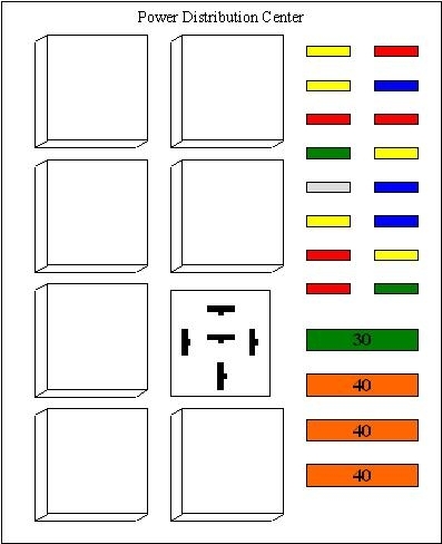
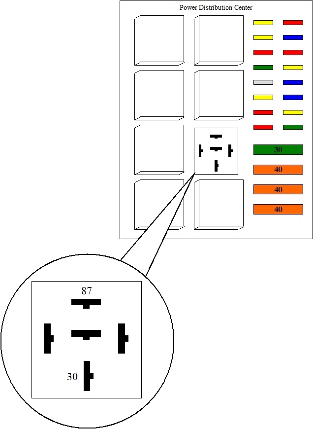
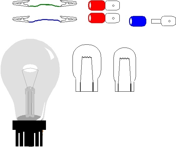
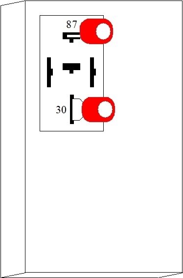
The last 6 drawings show the procedure in a dumbed-down way. I apologize for that, but it's easier to just post everything in my original format. Also, I can't find a drawing showing the individual terminals for the starter relay. Use the one that has 12 volts all the time. For the second one, you may have to experiment to figure out which one goes to the solenoid.
Images (Click to enlarge)
Jun 13, 2022 at 12:58 PM