Okay, I posted the description of the system and how it works with ABS and traction control issues. When you disable that system, it disables traction control. When you disable the traction control, it will default to 2 wheel drive.
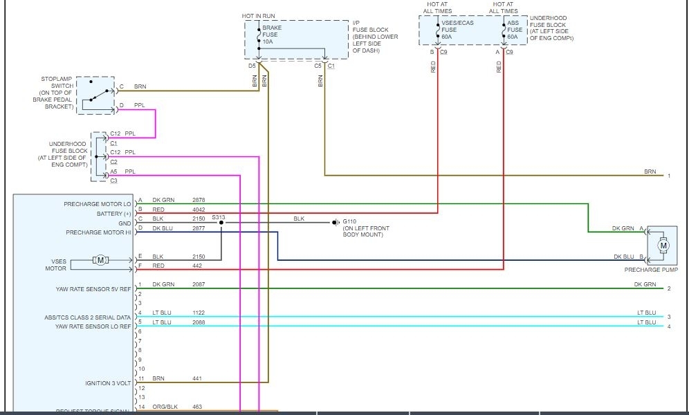
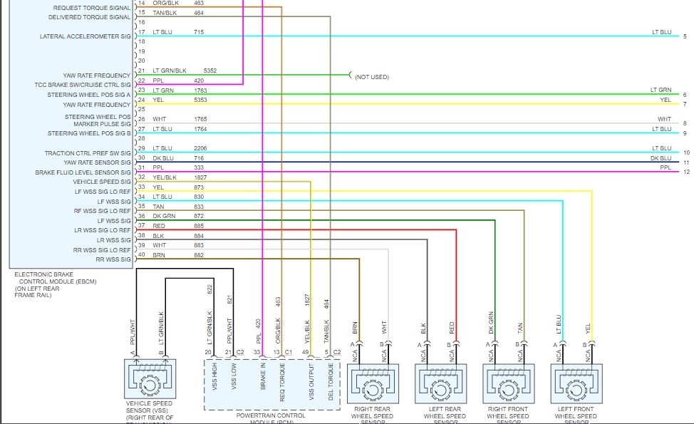
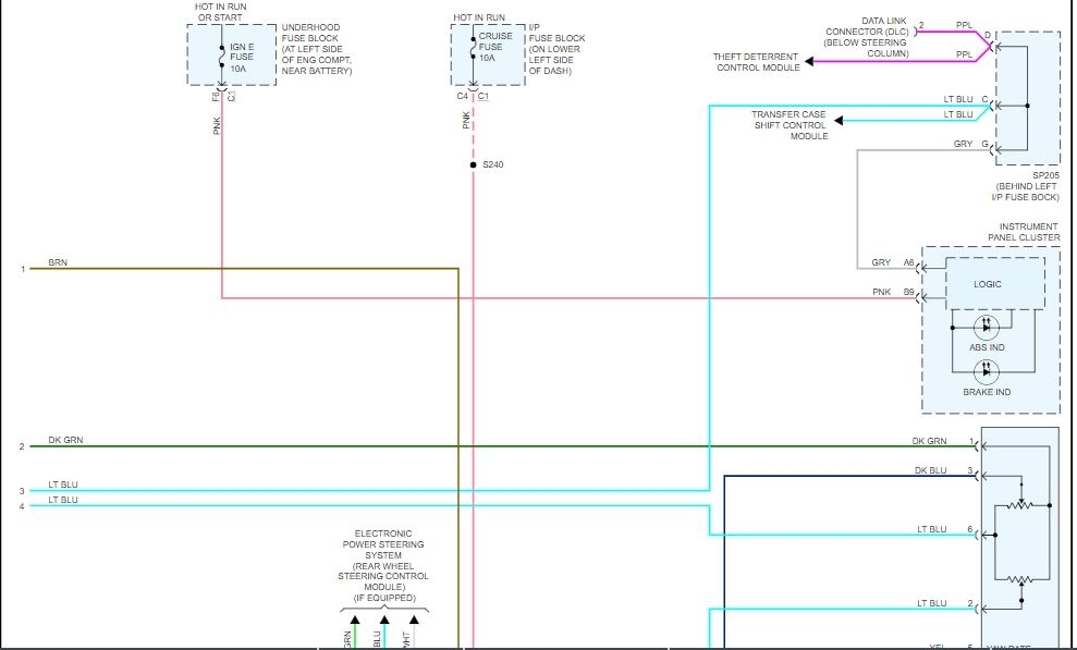
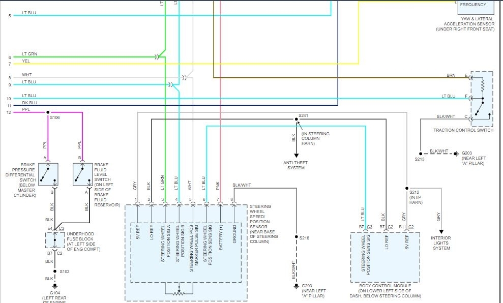
I attached the wiring diagram for the system as well. It will default to 2 wheel when there is an issue.
https://www.2carpros.com/articles/how-to-check-wiring
Roy
ABS Description and Operation (W/JL4)
Vehicles with RPO JL4 are equipped with an EBC 430EV ABS/DRP/TCS/VSES module.
This module provides the following vehicle performance enhancement systems.
^ Antilock Brake System (ABS)
^ Dynamic Rear Proportioning (DRP)
^ Traction Control System (TCS)
^ Vehicle Stability Enhancement System (VSES)
The following components are involved in the operation of the above systems.
^ Electronic brake control module (EBCM) - The EBCM controls the system functions and detects failures.The EBCM contains the following components.
^ System relay - The system relay is internal to the EBCM. The system relay is energized when the ignition is ON. The system relay supplies battery positive voltage to the valve solenoids and to the ABS pump motor. This voltage is referred to as system voltage.
6 Solenoids - The solenoids are commanded ON and OFF by the EBCM to operate the appropriate valves in the brake pressure modulator valve (BPMV).
^ Longitudinal Accelerometer - The EBCM uses the longitudinal accelerometer to determine the actual straight-line acceleration of the vehicle.
^ Brake pressure modulator valve (BPMV) - The BPMV uses a 4-circuit configuration to control hydraulic pressure to each wheel independently.The BPMV contains the following components.
^ ABS pump motor and pump
^ Four isolation valves
^ Four dump valves
^ Two TC isolation valves
^ Two TC supply valves
^ A master cylinder pressure sensor
^ A front low-pressure accumulator
^ A rear low-pressure accumulator
^ Wheel speed sensors (WSS) - As the wheels spin, toothed rings interrupt magnetic fields in the wheel speed sensors. This causes each wheel speed sensor to generate an AC signal. The EBCM uses these AC signals to calculate the wheel speed. Any imperfections in the toothed ring, such as a missing or damaged tooth, can cause an inaccurate WSS signal.
^ Traction control switch - VSES and the engine torque reduction function of TCS are manually disabled or enabled by pressing the traction control switch.
^ Lateral accelerometer - The EBCM uses the lateral accelerometer to determine the sideways acceleration of the vehicle. The lateral accelerometer is packaged with the yaw rate sensor as a single component.
^ Master cylinder pressure sensor - The master cylinder pressure sensor is located within the BPMV. The master cylinder pressure sensor uses a 5-volt reference and generates an output signal proportionate to the hydraulic fluid pressure which is present in the front brake circuit at the master cylinder.
^ Yaw rate sensor - The EBCM uses the yaw rate sensor to determine the rate of rotation along the vehicle's vertical axis. The yaw rate sensor is packaged with the lateral accelerometer as a single component.
^ Steering wheel position sensor - The electronic brake control module (EBCM) receives several inputs from the steering wheel position sensor. 3 digital square wave signal inputs are wired directly to the EBCM harness connector, however, only signals A and B are used or monitored. The failure of the index pulse signal does not effect VSES function. The body control module (BCM), which receives an analog steering position sensor input, transmits steering position data on the serial data line. The EBCM monitors the serial data information as an added fail-safe for the steering position sensor circuitry. Battery voltage is supplied to the digital portion of the steering wheel position sensor from the cruise control fuse. The analog portion of the steering wheel position sensor is supplied a 5-volt reference from the BCM. This circuit is also used for a lamp dimming function.
^ Precharge pump motor and pump - The precharge pump assembly is used to assist the ABS pump in rapidly building hydraulic pressure needed during certain TCS or VSES events.
Antilock Brake System (ABS)
When wheel slip is detected during a brake application, an ABS event occurs. During antilock braking, hydraulic pressure in the individual wheel circuits is controlled to prevent any wheel from slipping. A separate hydraulic line and specific solenoid valves are provided for each wheel. The ABS can decrease, hold, or increase hydraulic pressure to each wheel. The ABS does not, however, increase hydraulic pressure above the amount which is transmitted by the master cylinder during braking.
During antilock braking, a series of rapid pulsations is felt in the brake pedal. These pulsations are caused by the rapid changes in position of the individual solenoid valves as the EBCM responds to wheel speed sensor inputs and attempts to prevent wheel slip. These pedal pulsations are present only during antilock braking and stop when normal braking is resumed or when the vehicle comes to a stop. A ticking or popping noise may also be heard as the solenoid valves cycle rapidly. During antilock braking on dry pavement, intermittent chirping noises may be heard as the tires approach slipping. These noises and pedal pulsations are considered normal during antilock operation.
Vehicles equipped with ABS may be stopped by applying normal force to the brake pedal. Brake pedal operation during normal braking is no different than that of previous non-ABS systems. Maintaining a constant force on the brake pedal provides the shortest stopping distance while maintaining vehicle stability. The typical ABS activation sequence is as follows.
Pressure Hold
The EBCM closes the isolation valve and keeps the dump valve closed in order to isolate the slipping wheel when wheel slip occurs. This holds the pressure steady on the brake so that the hydraulic pressure does not increase or decrease.
Pressure Decrease
If a pressure hold does not correct the wheel slip condition, a pressure decrease occurs. The EBCM decreases the pressure to individual wheels during deceleration when wheel slip occurs. The isolation valve is closed and the dump valve is opened. The excess fluid is stored in the accumulator until the pump can return the fluid to the master cylinder or fluid reservoir.
Pressure Increase
After the wheel slip is corrected, a pressure increase occurs. The EBCM increases the pressure to individual wheels during deceleration in order to reduce the speed of the wheel. The isolation valve is opened and the dump valve is closed. The increased pressure is delivered from the master cylinder.
Dynamic Rear Proportioning (DRP)
The dynamic rear proportioning (DRP) is a control system that enhances the hydraulic proportioning function of the mechanical proportioning valve in the base brake system. The DRP control system is part of the operation software in the EBCM. The DRP uses active control with existing ABS in order to regulate the vehicle's rear brake pressure.
Traction Control System (TCS)
Traction is maintained by limiting the amount of torque produced by the drivetrain and also by applying brake pressure to slipping wheels during acceleration. This causes power to transfer through the driveline to wheels which are not slipping. The transfer case used on 4 wheel drive vehicles equipped with VSES does not contain a viscous coupling and therefore allows the front and rear driveshafts to turn at substantially different speeds. This front to rear differential must be kept within acceptable parameters by the VSES. The two methods of traction control are performed as follows.
Engine torque reduction
The EBCM uses a 5-volt pulse width modulated (PWM) signal to request that the PCM reduce the amount of torque to the drive wheels. The PCM reduces torque to the drive wheels by retarding spark timing and commanding the throttle actuator control. The PCM uses a 12-volt PWM signal to report to the EBCM the amount of torque that is being delivered to the drive wheels. Engine torque reduction is mostly used to reduce vehicle speed during VSES events and during TCS events when the brakes are in danger of being overheated or all of the driven wheels are slipping at the same rate. Engine torque reduction can be disabled by pressing the traction control switch.
Brake pressure application
The EBCM uses brake pressure application to control traction by transferring torque through the driveline to wheels which are not slipping. The precharge pump motor, ABS pump motor and appropriate valve solenoids are commanded ON and OFF to apply brake pressure to the slipping wheels. Brake pressure application is used in an attempt to maintain equal WSS signals at the driven wheels.
The EBCM does not allow excessive brake pressure application due to the fact that the solenoid coils or the brakes may become overheated, damaging the EBCM or reducing the driver's ability to stop the vehicle. Estimated coil and brake temperatures are determined by a calculation in the EBCM software. Overheated solenoid coils cause all brake pressure application to become disabled and the stability system disabled message to be displayed. Overheated brakes cause brake pressure application during TCS events to disable, yet the VSES remains functional and as long as the engine torque reduction is enabled, there is no indication to the driver when this occurs and no DTC sets. In either case, engine torque reduction is the only function governing front to rear differential speeds within the transfer case on 4 wheel drive vehicles. Also on 4 wheel drive vehicles, if the engine torque reduction is disabled for any reason when brake application disables, the traction off indicator flashes if wheel slip is detected. Any time the traction off indicator is flashing, there is danger of transfer case damage.
Vehicle Stability Enhancement System (VSES)
VSES provides added stability during aggressive maneuvers. Yaw rate is the rate of rotation about the vehicle's vertical axis. The VSES is activated when the EBCM determines that the desired yaw rate does not match the actual yaw rate as measured by the yaw rate sensor.
The desired yaw rate is calculated by the EBCM using, primarily, the following inputs.
^ The position of the steering wheel
^ The speed of the vehicle
^ The lateral, or sideways acceleration of the vehicle
The difference between the desired yaw rate and the actual yaw rate is the yaw rate error, which is a measurement of oversteer or understeer. When a yaw rate error is detected, the EBCM attempts to correct the vehicle's yaw motion by applying brake pressure to one or more of the wheels. The amount of brake pressure which is applied varies, depending on the correction required. The engine torque may be reduced also, if it is necessary to slow the vehicle while maintaining stability.
VSES activations generally occur in turns during aggressive driving. When braking during VSES activation, the pedal may pulsate. The brake pedal pulsates at a higher frequency during VSES activation than during ABS activation.
System Pre-Fill
This vehicle is equipped with a 4-wheel disc brake system. Disc brake calipers are designed so that when hydraulic pressure is not being applied, the caliper piston lip seal causes the piston to retract, creating measurable clearance between the brake pads and the rotor. Since a small amount of brake fluid must be delivered to the calipers before any actual braking occurs, the VSES uses system pre-fill to prevent delayed brake application and enhance system performance. If the EBCM determines that a brake application is likely to be needed, the ABS pump motor runs momentarily to take up any clearances between the brake pads and the rotor. By monitoring the master cylinder pressure sensor feedback signal, the EBCM can determine when the brake pads are contacting the rotor. The EBCM then holds this small amount of pressure in the system.
A VSES brake application may or may not occur after pre-fill is complete. If the EBCM determines that a brake application is no longer pending, the pre-fill pressure is released and the VSES system returns to the normal, monitoring state.
The reason that we must understand system pre-fill is that pre-fill may lead to customer concerns. Any time the ABS pump motor is active, the motor draws a large amount of current, and may cause the vehicle lighting systems to dim noticeably. When ABS activity occurs, most drivers understand that this activity is the cause of noises and dimming lights. Likewise, when an actual VSES event occurs, the Stability System Active message is displayed, which helps drivers understand why these other conditions occur. Since pre-fill is not an actual VSES event, but preparation for a pending event, no message is displayed. Also, system noise during pre-fill is very minimal. A customer may become concerned with what is perceived to be an electrical problem, due to the intermittent dimming lights, when, in fact, no malfunction exists and the condition is normal.
Precharge Pump
The TCS and VSES are dependant on the precharge pump to assist the ABS pump in building hydraulic pressure to perform brake pressure application. This is because the passages from the master cylinder reservoir to the ABS pump inlet are restrictive, and do not supply adequate fluid to the ABS pump. The precharge pump is used mostly at the beginning of brake pressure applications since once some pressure is built, the ABS pump is usually able to continue building pressure and maintain the application. The precharge pump inlet is fed by a flexible hose which draws fluid directly from a port on the master cylinder reservoir. When the precharge pump is activated, fluid is pumped into the combination valve, slightly pressurizing the front and rear brake circuits between the master cylinder and the BPMV. It is important to note that during this time, the EBCM must isolate of the all wheels except for those to which the brake pressure application is directed. The portion of the pressurized fluid that is not drawn into the ABS pump inlet, passes through the bypass ports in the master cylinder and returns to the reservoir. Some of the pressurized fluid is supplied to the ABS pump inlet when the EBCM commands ON a supply valve in the BPMV. Since the fluid at the ABS pump inlet is slightly pressurized, the ABS pump is able to function with higher efficiency. The precharge pump, however, is not always used during TCS or VSES events due to the fact that the precharge pump motor must be protected from overheating. During a long series of brake pressure applications, the precharge pump may be disabled by the EBCM for up to 12 seconds. Although the driver may be able to detect a change in the vehicle stability during this time, the TCS and VSES do remain functional. No indication is given to the driver if the precharge pump is disabled due to overheating.
Power-up Self-Test
The EBCM is able to detect many malfunctions whenever the ignition is ON. However, certain failures cannot be detected unless active diagnostic tests are performed on the components. Shorted solenoid coil or motor windings, for example, cannot be detected until the components are commanded ON by the EBCM. Therefore, a power-up self-test is required at the beginning of each ignition cycle to verify correct operation of components before the various control systems can be enabled. The EBCM performs the first phase of the power-up self-test when the ignition is first turned ON. The system relay, solenoids and the ABS pump motor are commanded ON and OFF to verify proper operation and the EBCM verifies the ability to return the system to base braking in the event of a failure. The master cylinder pressure sensor performs a self-test by sending a series of specific voltage signals to the EBCM, each for a predetermined amount of time. This phase of the power-up self-test may be heard by the driver, depending on how soon the engine is cranked and started after turning ON the ignition. The second phase of the power-up self-test begins when the vehicle is driven at a speed greater than 16 km/h (10 mph) and the EBCM has not detected any TCS/VSES related malfunctions thus far. During this phase, the precharge pump is tested to verify the ability to build adequate pressure to perform brake pressure application during certain TCS and VSES events. When the brake switch indicates that the brake is not applied and the master cylinder pressure is detected as being low, the EBCM proceeds with the test. The EBCM isolates all of the wheels by closing the four isolation valves. The precharge pump is then commanded ON while the EBCM monitors the master cylinder pressure sensor input. The precharge pump must build approximately 248 kPa (36 psi) of hydraulic pressure within 1 second or the test is failed. If the EBCM uses brake pressure application to perform TCS or VSES prior to the second phase of the power-up self-test, the precharge pump is tested at this time and the second phase of the test is not required. Due to the fact that all of the wheels are isolated during the second phase of the test, the test must be aborted if the brake is applied while the test is being performed. Occasionally, the driver may detect this by experiencing a momentary hard pedal.
VSES Sensors Initialization
The VSES sensors values may vary slightly due to differences in temperature, sensor mounting, connector resistances, manufacturing, etc. Since VSES is a very sensitive and precise control system, it is imperative that the EBCM be able to accurately equate a given sensor voltage with an actual unit of measurement. For example, the yaw rate signal of one vehicle may be 2.64 volts at +18.0 deg/sec yaw rate while the yaw rate signal of another vehicle may be 2.64 volts at +17.5 deg/sec yaw rate. Therefore, at the beginning of each ignition cycle, the EBCM must perform an initialization procedure to observe how the VSES sensors are correlated with each other and also to determine what each sensor value is when the applicable unit of measurement equals 0. This voltage is referred to as the sensor bias voltage. Although some activation of the VSES system may occur if required to prior to full initialization, the system does not give optimum performance until the sensors are fully initialized.
The following VSES sensors require initialization.
^ The yaw rate sensor
^ The lateral accelerometer
^ The longitudinal accelerometer
^ The master cylinder pressure sensor
^ The steering wheel position sensor
When the vehicle speed is greater than 25 km/h (15 mph), full sensor initialization must occur during 3 km (1.8 mi) of driving or 1 km (0.6 mi) of straight and stable driving, whichever occurs first. Although an attempt at initialization may fail due to driving conditions, such as driving on a very winding road, failed initialization is usually caused by a sensor bias voltage which is not within an acceptable range. Often, a DTC sets soon after a failed initialization attempt. The message center displays the stability system disabled message when sensor initialization fails.
ECE 13 Response
The EBCM illuminates the ABS indicator when a malfunction which disables ABS is detected. Usually, the ABS indicator is turned OFF during the following ignition cycle unless the fault is detected during that ignition cycle. However, the setting of a wheel speed sensor related DTC causes the ABS indicator to remain illuminated during the following ignition cycle until the vehicle is operated at a speed greater than 13 km/h (8 mph). This allows the EBCM to verify that no malfunction exists, before turning OFF the ABS indicator. This reaction occurs even if the ABS indicator turns OFF when the scan tool is used to clear the DTCs. When repairing these vehicles, it is important to ensure that the ECE 13 response has occurred and that the ABS indicator does not illuminate after returning the vehicle to the customer. It is also important to verify that ECE 13 is not the cause of an ABS indicator which is illuminated when no DTCs are set, before attempting to diagnose other possible causes.
Driver Information Indicators and Messages
The following indicators are used to inform the driver of several different factors.
Brake Warning Indicator
The instrument panel cluster (IPC) illuminates the brake warning indicator when the following occurs.
^ The body control module (BCM) detects that the park brake is engaged. The IPC receives a serial data message from the BCM requesting illumination. The brake warning indicator flashes at a rate of approximately twice per second when the park brake is engaged.
^ The EBCM detects a low brake fluid condition or a base brake pressure differential and sends a serial data message to the IPC requesting illumination.
^ The IPC performs the bulb check.
^ The EBCM detects an ABS-disabling malfunction which also disables dynamic rear proportioning (DRP) and sends a serial data message to the IPC requesting illumination.
ABS Indicator
The IPC illuminates the ABS indicator when the following occurs.
^ The electronic brake control module (EBCM) detects an ABS-disabling malfunction and sends a serial data message to the IPC requesting illumination.
^ The IPC performs the bulb check.
^ The IPC detects a loss of serial data communication with the EBCM.
^ A DTC is set during the previous ignition cycle which requires an ECE 13 response at the beginning of the current ignition cycle. The EBCM sends a serial data message to the IPC requesting illumination.
Traction Off Indicator
The IPC illuminates the traction off indicator when the following occurs.
^ The EBCM disables engine torque reduction due to a malfunction and sends a serial data message to the IPC requesting illumination.
^ The driver manually disables VSES and engine torque reduction by pressing the traction control switch. The EBCM sends a serial data message to the IPC requesting illumination.
The IPC flashes the traction off indicator if wheel slip is detected while engine torque reduction and brake pressure application are both disabled.
Service Brake System Message
The service brake system message is displayed whenever the red brake warning indicator is illuminated.
Stability System Active Message
The message center displays the stability system active message when a TCS or VSES event occurs. The EBCM sends a serial data message to the IPC requesting this display.
Stability System Disabled Message
The message center displays the stability system disabled message when one or more of the following conditions exists.
^ The transfer case is shifted into 4 LO. The EBCM sends a serial data message to the IPC requesting illumination.
^ The driver manually disables the VSES and engine torque reduction by pressing the traction control switch. The EBCM sends a serial data message to the IPC requesting illumination.
^ The estimated temperature of any solenoid coil exceeds an acceptable limit. The EBCM sends a serial data message to the IPC requesting this display.
^ The EBCM detects a failed brake switch. The EBCM sends a serial data message to the IPC requesting this display. A DTC sets when this condition exists.
^ The EBCM detects that the brake fluid level is low or a base brake pressure differential exists. These two conditions are not distinguishable by the EBCM. The EBCM sends a serial data message to the IPC requesting this display.
^ VSES sensor initialization time is excessive. The EBCM sends a serial data message to the IPC requesting this display.
^ Serial data communication between the EBCM and any of several other control modules is interrupted. The EBCM sends a serial data message to the IPC requesting this display or the IPC displays the message when communication with the EBCM is interrupted.
^ The PCM is not able to perform engine torque reduction. The EBCM sends a serial data message to the IPC requesting this display. DTCs set when this condition exists.
^ The EBCM detects an excessively low or excessively high ignition voltage. The EBCM sends a serial data message to the IPC requesting this display.
Service Stability System Message
The message center displays the service stability system message when any one of many VSES-disabling DTCs is set. The EBCM sends a serial data message to the IPC requesting this display.
Traction Active Message
The drive information center displays the traction active message when engine torque reduction or brake pressure application is required to maintain traction. The EBCM sends a serial data message to the IPC requesting this display.
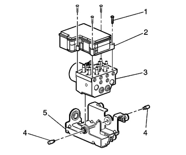
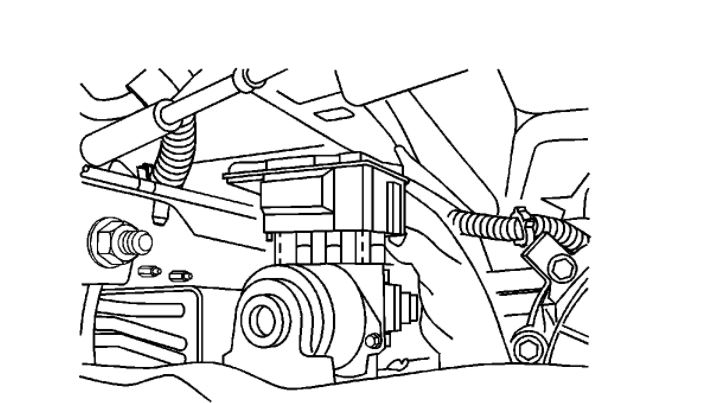
Images (Click to enlarge)
Jan 22, 2021 at 8:24 PM