Welcome back:
It is called an OBD 2 scanner. And it will need to be plugged into the OBD port under the dash of the vehicle. To read the codes will require a higher level scanner. The lower cost ones are designed to only read power-train codes.
Here is a flow chart related to the SRS light not turning off. Take a look through it. It is somewhat involved. The attached pictures correlate with the directions.
Note: This information is for an Accord. I will not have the specifics for your vehicle, but wanted you to see the process.
____________________________
The SRS Indicator Light Doesn't Go Off
1. Erase the DTC memory.
2. Turn the ignition switch ON, and check that the SRS indicator light comes on for about six seconds and goes off.
Does the SRS indicator light stay on?
YES - Go to step 3.
NO - Intermittent failure, system is OK at this time. See Troubleshooting Intermittent Failures. See: Air Bag Systems > Initial Inspection and Diagnostic Overview > Troubleshooting Intermittent Failures
3. Turn the ignition switch OFF.
4. Check for blown No. 2 (10 A) fuse in the under-dash fuse/relay box.
Is the fuse OK?
YES - Go to step 8.
NO - Go to step 5.
5. Replace the No. 2 (10 A) fuse.
6. Erase the DTC memory.
7. Turn the ignition switch ON.
Does the SRS indicator light go off after six seconds?
YES - The system is OK.
NO - Confirm the DTC, and continue troubleshooting.
8. Disconnect the battery negative cable, and wait for three minutes.
9. Disconnect the driver's and front passenger's airbag connectors.
10. Disconnect the SRS main harness 18P connector from the SRS unit.
11. Reconnect the battery negative cable.
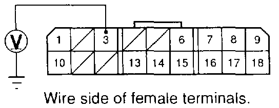
SRS Main Harness 18P Connector
pic 1
12. Connect a voltmeter between the No. 3 terminal (+) of the SRS main harness 18P connector and ground.
13. Turn the ignition switch ON.
Is there battery voltage?
YES - Go to step 14.
NO - Open in the SRS main harness (VB line); replace the harness.
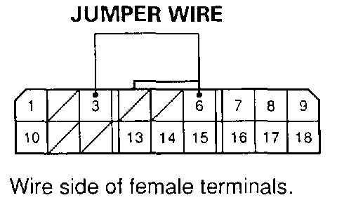
SRS Main Harness 18P Connector
pic 2
14. Connect the SRS main harness 18P connector terminals No. 6 and No. 3 with a jumper wire and backprobe adapters.
Does the SRS indicator light go off?
YES - Faulty SRS unit or poor contact at the SRS main harness 18P connector; check the connector. If the connector is OK, replace the SRS unit.
NO - Go to step 15.
15. Check the No.2 (10 A) fuse. Did fuse No. 2 (10 A) blow?
YES - Go to step 16.
NO - Go to step 19.
16. Turn the ignition switch OFF.
17. Disconnect the dashboard wire harness 16P connector from the gauge assembly.
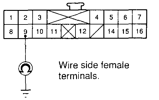
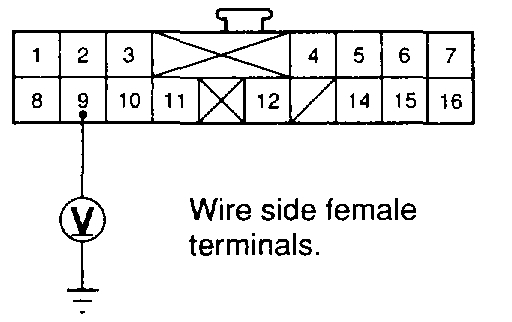
SRS Main Harness 16P Connector
pic 3
18. Check resistance between the No. 9terminal of the dashboard wire harness 16P connector and ground. There should be 1 M Ohm or more.
Is the resistance as specified?
YES - Short to ground in the gauge assembly; replace the gauge assembly.
NO - Go to step 26.
19. Turn the ignition switch OFF.
20. Remove the gauge assembly. Do not disconnect the connector from the gauge assembly.
21. Turn the ignition switch ON.
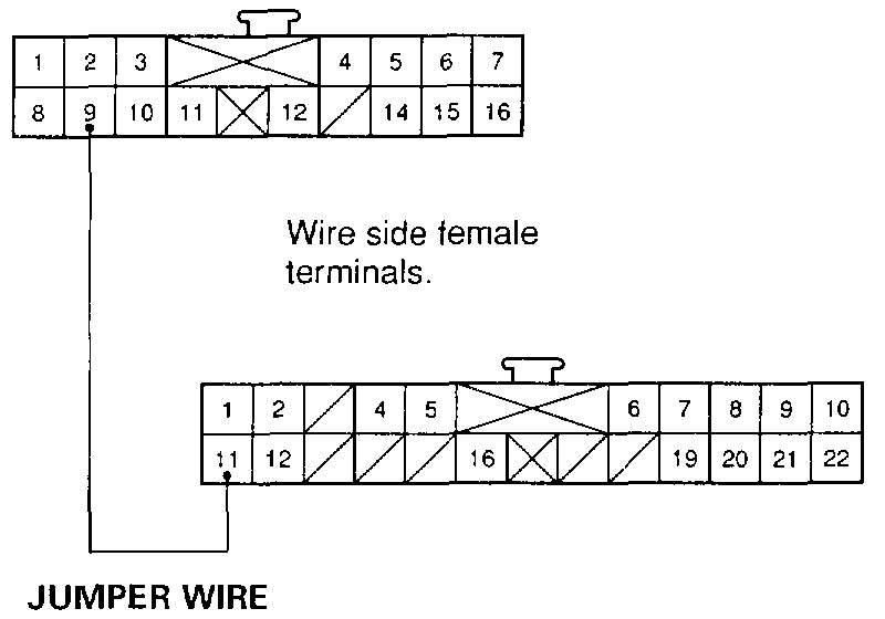
SRS Main Harness 16P And 22P Connector
pic 4
22. Connect the No. 9 terminal of the dashboard wire harness 16P connector and No.11 terminal of the dashboard wire harness 22P connector with a jumper wire.
Does the SRS indicator light go off?
YES - Go to step 23.
NO - Faulty SRS indicator light circuit in the gauge assembly; replace the SRS printed circuit board in the gauge assembly.
23. Turn the ignition switch OFF.
24. Disconnect the dashboard wire harness 16P connector from the gauge assembly.
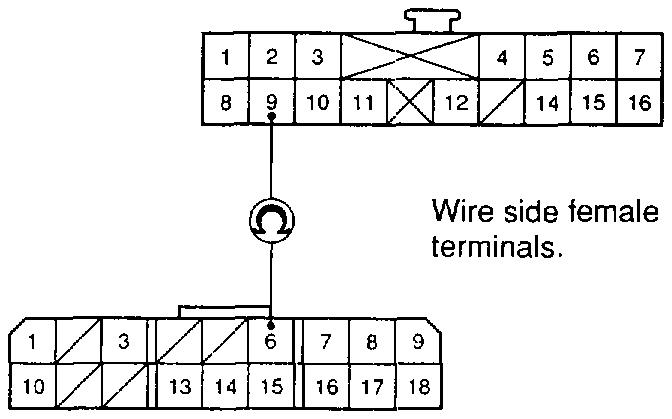
SRS Main Harness 16P And 18P Connector
pic 5
25. Check resistance between the No. 6 terminal of the SRS main harness 18P connector and No. 9 terminal of the dashboard wire harness 16P connector; there should be 0 - 1.0 Ohm.
Is the resistance as specified?
YES - Go to step 28.
NO - Go to step 31.
26. Disconnect the SRS main harness 3P connector from the dashboard wire harness.
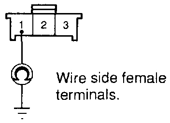
SRS Main Harness 3P Connector
pic 6
27. Check resistance between the No. 1 terminal of the SRS main harness 3P connector and ground. There should be 1 M Ohm or more.
Is the resistance as specified?
YES - Short to ground in the dashboard wire harness; repair the dashboard wire harness.
NO - Short to ground in the SRS main harness; replace the SRS main harness.
28. Reconnect the SRS main harness 18P connector to the SRS unit.
SRS Main Harness 16P Connector
pic 7
29. Connect a voltmeter between the No. 9 terminal (+) of the dashboard wire harness 16P connector and ground.
30. Turn the ignition switch ON, wait for six seconds, then measure voltage.
Is there 8.5 V or more?
YES - The problem corrected itself after disconnecting and connecting the connectors. Be sure all terminals make good contact, and recheck the system (see Troubleshooting Intermittent Failures)
NO - Poor contact at the SRS main harness 18P connector; check the connector.
- If the connector is OK, substitute a known-good SRS unit, and recheck.
- If the connector is damaged, replace the SRS main harness.
31. Disconnect the SRS main harness 3P connector from the dashboard wire harness.
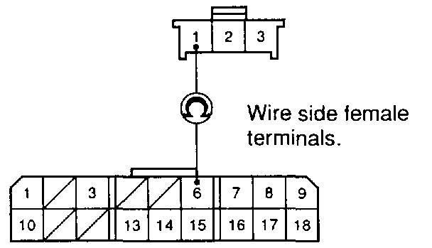
SRS Main Harness 18P Connector
pic 8
32. Check resistance between the No. 6 terminal of the SRS main harness 18P connector and No. 1 terminal of the SRS main harness 3P connector; there should be 0 - 1.0 Ohm
Is the resistance as specified?
YES - Open in the BLU wire of the dashboard wire harness; repair the dashboard wire harness.
NO - Open in the SRS main harness; replace the SRS main harness.
+++++++++++++++++++++++++++++++++++++++++++++++++++++++++++++
As you can see, it can become somewhat involved.
Let me know if you have questions.
Take care,
Joe
Images (Click to make bigger)
Sunday, May 19th, 2019 AT 6:25 PM