Welcome to 2CarPros.
Here is what I have specific to the cams. Let me know if it helps. Also, the attached pics correlate with the directions.
__________________________
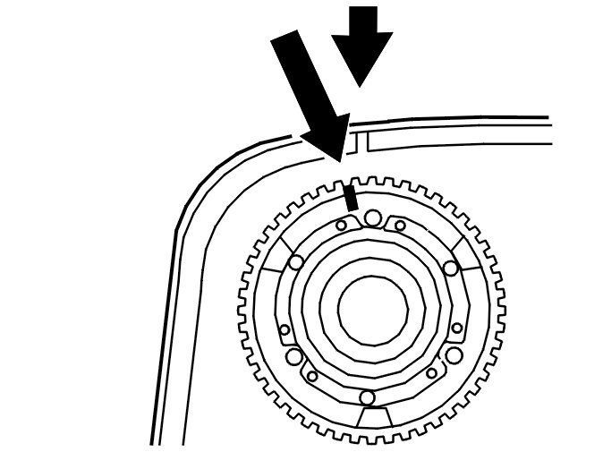
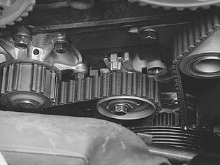
Installing the timing gear pulley for the camshafts
Note! The purpose of the "Installing the timing gear pulley" section described here is to ensure that the VVT unit is correctly positioned and to reset the camshaft timing gear pulley to the correct position using the markings made at the factory. This is to ensure that the conditions are correct for any later fault-tracing.
pic 1
Note! Do not turn counter clockwise during this procedure.
Slacken off, but do not remove, the screws which secure the timing gear pulley to the variable valve timing unit.
Press the variable valve timing unit and timing gear pulley onto the camshaft.
Install the center screw which secures the variable valve timing unit to the camshaft. Tighten slightly. Turn the variable valve timing unit counter-clockwise as far as it will go. Remove the center screw.
Position the upper timing cover.
Turn the timing gear pulley clockwiseuntil the screws at the oval holes are in the limit position. Continue turning clockwise until the timing gear pulley marking is 1 cogs before the marking on the upper timing cover.
Check that the timing gear pulley is still in the limit position in the oval holes. Tighten the center screw in the variable valve timing unit. Tighten. See Tightening torque See: Engine > Mechanical > Tightening Torque.
Check that the variable valve timing unit does not rotate when tightening. Install and tighten the center plug. See Tightening torque See: Engine > Mechanical > Tightening Torque.
Turn the variable valve timing unit clockwise to the limit position.
Turn the timing gear pulley so that the markings correspond.
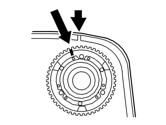
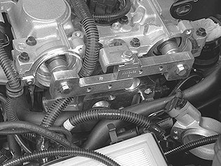
Installing the variable valve timing (VVT) unit on the intake camshaft
pic 2
Note! Do not turn counter clockwise during this procedure.
Slacken off, but do not remove, the screws which secure the timing gear pulley to the variable valve timing unit. Press the variable valve timing unit and timing gear pulley onto the camshaft.
Install the center screw which secures the variable valve timing unit to the camshaft. Tighten slightly.
Turn the variable valve timing unit counter-clockwise as far as it will go. Remove the center screw. Position the upper timing cover.
Turn the timing gear pulley clockwise until the screws at the oval holes are in the limit position. Continue turning clockwise until the timing gear pulley marking is 1-1/2 cogs before the marking on the upper timing cover.
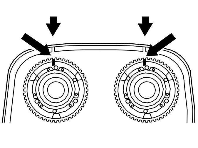
pic 3
Check that the timing gear pulley is still in the limit position in the oval holes.
Tighten the center screw in the VVT unit. See Tightening torque See: Engine > Mechanical > Tightening Torque.
Check that the variable valve timing unit does not rotate when tightening. Install the center plug. Tighten. See Tightening torque See: Engine > Mechanical > Tightening Torque.
Turn the variable valve timing unit clockwise to the limit position. Turn the timing gear pulley so that the markings correspond.
Finishing
Tighten the center screw on the timing belt tensioner. Tighten to 5 Nm.
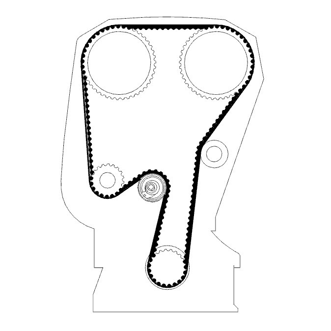
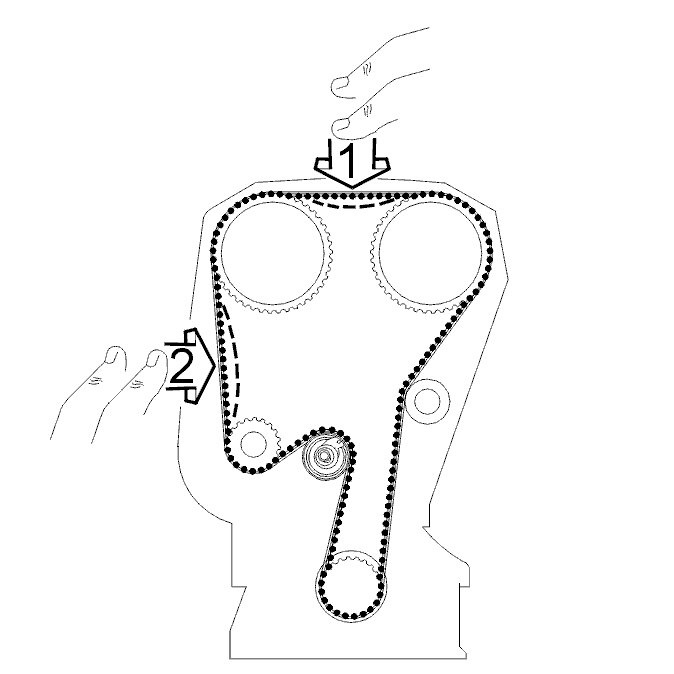
Installing the timing belt
pic 4
Install the belt in the following order:
- crankshaft
- the idler pulley
- intake camshaft
- exhaust camshaft
- coolant pump
- belt tensioner.
Note! The variable valve timing units do not have a return spring and are easily dislodged when reinstalling the timing belt. Check that the markings are correct.
Adjusting the timing belt
pic 5
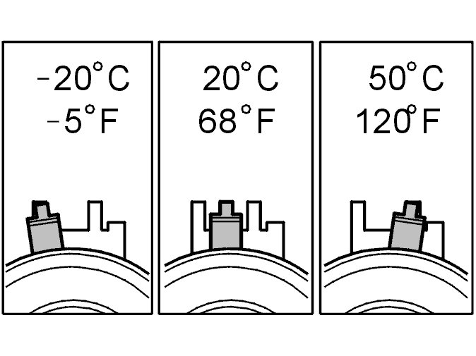
This adjustment is to be made with a cold engine. A suitable temperature is approximately 20°C/68°F.
At higher temperatures (with the engine at operating temperature or a high outside temperature for example) the indicator is further to the right.
The illustration shows the position of the indicator when aligning the timing belt tensioner at different temperatures.
Hold the center screw secure and turn the belt tensioner eccentric clockwise until the tensioner indicator passes the marked position and reaches the limit position.
Tighten the 3 screws on the exhaust camshaft timing gear pulley. Tighten. See Tightening torque See: Engine > Mechanical > Tightening Torque.
Tighten the 3 screws on the intake camshaft timing gear pulley. Tighten. See Tightening torque See: Engine > Mechanical > Tightening Torque.
pic 6
Note! Check that the variable valve timing units are in the limit position.
Turn the eccentric back so that the indicator reaches the marked position in the center of the window.
Remember to hold the center screw secure at the same time.
Hold the eccentric secure. Tighten the center screw. Tighten. See Tightening torque See: Engine > Mechanical > Tightening Torque.
Check that the indicator is in the correct position.
pic 7
Remove:
- camshaft adjustment tools 999 5452 CAMSHAFT ADJUSTMENT TOOL See: Vehicle > Electrical / Mechanical Repair > 999 5452 Camshaft Adjustment Tool from the rear edge of the camshafts
- crankshaft stop 999 5451 ADJUSTMENT TOOL See: Vehicle > Electrical / Mechanical Repair > 999 5451 Adjustment Tool
- the plug with a new sealing washer. Tighten. See Tightening torque See: Engine > Mechanical > Tightening Torque.
Checking the markings and belt tension
pic 8
Press the timing belt to check that the indicator on the belt tensioner moves easily.
Position the upper timing cover.
Turn the crankshaft 2 rotations and check that the markings on the crankshaft and camshaft pulleys correspond.
Check that the indicator on the belt tensioner is within the marked area.
Remove the upper timing cover.
____________________
Let me know if this helps.
Joe
Images (Click to enlarge)
Oct 19, 2019 at 10:12 PM