Circuit Description
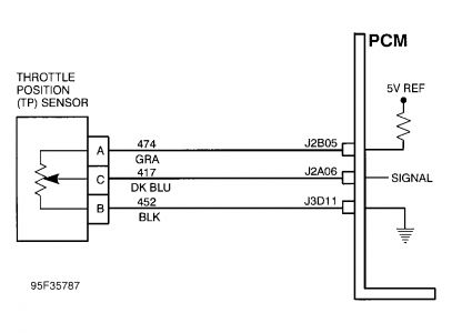
Throttle Position (TP) sensor is a variable resistor. TP sensor input voltage will be low when throttle blade is closed and increase when throttle is opened.
DTC will set if TP sensor voltage is less than .2 volt with engine running and no other TP sensor DTC(s) have been set. DTC P1122 sets in about .5 second while DTC P0122 takes 3 seconds. TP sensor signal is continuously monitored.
Diagnostic Procedures
1.Connect scan tool. Check if DTC P1635 is also present. If DTC P1635 is present, diagnose this DTC first. If DTC P1635 is not present, go to next step.
2.Using scan tool, monitor TP sensor voltage reading. If TP sensor reads less than .2 volt, go to next step. If TP sensor reads greater than .2 volt, problem is intermittent. See DIAGNOSTIC AIDS.
3.Disconnect TP sensor harness connector. Using a jumper wire, jumper TP sensor harness connector terminals "A" and "C". If TP sensor still reads less than .2 volt, go to next step. If TP sensor reads greater than .2 volt, check tightness of harness connector terminals or faulty TP sensor.
4.Remove jumper wire. Using a test light connected to battery voltage, probe TP sensor harness connector terminal "C". If TP sensor still reads less than .2 volt, go to next step. If TP sensor reads greater than .2 volt, check for open in 5-volt reference signal circuit to TP sensor (terminal "A".)
5.Turn ignition off. Disconnect PCM harness connectors J2 and J3. Check resistance between TP sensor harness connector terminals "B" and "C". If resistance is greater than 2 ohms, go to next step. If resistance is less than 2 ohms, check for shorted circuit between terminals "B" and "C" or circuit shorted to ground.
6.Check continuity of TP sensor signal circuit between PCM and sensor harness connector terminals. Repair as necessary. If circuit is okay, check tightness of harness connector terminals or faulty PCM.
Diagnostic Aids
Use scan tool to review malfunction history diagnostic information. This data can be used to duplicate a problem. Normal voltage readings should vary smoothly from .4 volt to 4.7 volts as throttle is moved from closed to wide open position.
Nov 14, 2008 at 10:00 PM