Hi and thanks for using 2CarPros.
First, if the check engine light stays on while the engine is running, you need to have the computer scanned to identify stored diagnostic trouble codes. These codes can help identify the issue. Here is a quick video that shows how it is done:
https://youtu.be/YV3TRZwer8k
I realize most people don't own a scanner. If that is the case, most parts stores will scan it for free. Do that and let me know the codes that are found.
Next, a common issue that causes a rough idle is an engine vacuum leak. If unmetered air enters the engine, the fuel / air mixture becomes too lean. The result is a rough idle, stalling.
Here is a link that shows how to perform a vacuum leak test:
https://www.2carpros.com/articles/how-to-use-an-engine-vacuum-gauge
Next, a dirty throttle body or plugged air filter can also be an issue. Take a look through these links. You may want to service the throttle body.
https://www.2carpros.com/articles/throttle-actuator-service
https://www.2carpros.com/articles/how-to-replace-a-car-air-filter
Here is another link you may find helpful. It discusses how to repair a backfire.
https://www.2carpros.com/articles/engine-backfires-while-running
Here are directions specific to your vehicle for performing a throttle body service. The attached pictures correlate with the directions.
______________________
THROTTLE BODY SERVICE
REMOVAL PROCEDURE
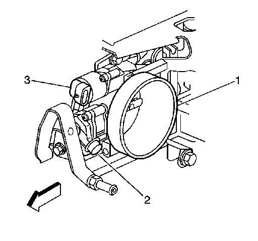
1. Disconnect the MAF sensor electrical connector.
Picture 1
2. Loosen the intake air duct clamps.
NOTE: Do not damage the MAF sensor screen. A damaged screen could restrict airflow and lead to a driveability concern.
3. Remove the mass air flow (MAF) sensor and air cleaner intake duct (2) as an assembly.
Picture 2
4. Inspect the throttle body bore (1) and throttle valve plate for deposits. Open the throttle valve to inspect all surfaces.
5. Clean the throttle body bore and throttle valve plate using a clean shop towel with GM Top Engine Cleaner, P/N 1052626 Canada P/N 993026, or AC-Delco Carburetor Tune-Up Conditioner, P/N X66-P, or equivalent product.
NOTE: Do not use any solvent that contains Methyl Ethyl Ketone (MEK). This solvent may damage fuel system components.
INSTALLATION PROCEDURE
NOTE: The outlet of the air cleaner assembly and the MAF sensor inlet duct must line up when completely installed. Misalignment may cause incorrect airflow readings resulting in MIL illumination or a driveability concern. An improperly installed inlet duct assembly or air cleaner assembly may cause misalignment.
Picture 3
1. Install the MAF sensor and air cleaner intake duct (2) as an assembly.
NOTE: Refer to Fastener Notice in Service Precautions.
2. Tighten the intake air duct clamps.
Tighten the intake air duct clamps to 3 N.m (27 lb in).
3. Connect the MAF sensor electrical connector to the MAF sensor.
__________________________________
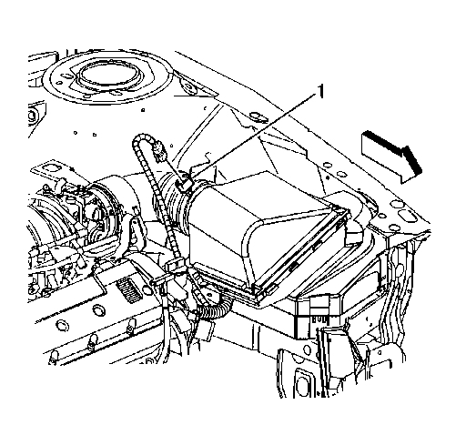
Next, you may want to consider cleaning the MAF sensor. Here is a link that shows in general how it is done.
https://www.2carpros.com/articles/mass-air-flow-service
Picture 4 shows the MAF location.
________________________________
If nothing helps, then you will need to check the idle air control valve (IAC). The IAC is responsible for maintaining engine idle speed. Here are directions / flow chart for diagnosing a bad IAC. Before going to all the trouble of testing everything on the flow chart, remove the IAC and check it for carbon build up. Also, check where it goes into the throttle body to confirm nothing is blocked.
IDLE AIR CONTROL (IAC) SYSTEM DIAGNOSIS
IDLE AIR CONTROL (IAC) SYSTEM DIAGNOSIS
CIRCUIT DESCRIPTION
The engine idle speed is controlled by the idle air control (IAC) valve. The IAC valve is on the throttle body. The IAC valve pintle moves in and out of an idle air passage bore to control air flow around the throttle plate. The IAC valve consists of a movable pintle, driven by a gear attached to an electric motor called a stepper motor. The stepper motor is capable of highly accurate rotation, or of movement, called steps. The stepper motor has 2 separate windings that are called coils. Each coil is supplied current by 2 circuits from the powertrain control module (PCM). When the PCM changes polarity of a coil, the stepper motor moves one step. The PCM uses a predetermined number of counts to determine the IAC pintle position. Observe IAC counts with a scan tool. The IAC counts will increment up or down as the PCM attempts to change the IAC valve pintle position. An IAC Reset will occur when the ignition key is turned OFF. First, the PCM will seat the IAC pintle in the idle air passage bore. Second, the PCM will retract the pintle a predetermined number of counts to allow for efficient engine start-up. If the engine idle speed is out of range for a calibrated period of time, an idle speed diagnostic trouble code (DTC) sets.
DIAGNOSTIC AIDS
Inspect for the following conditions:
- High resistance in an IAC valve control circuit
- The correct positive crankcase ventilation (PCV) valve, properly installed and proper operation of the PCV valve
- Proper operation and installation of all air intake components
- Proper installation and operation of the mass air flow (MAF) sensor, if equipped
- A tampered with or damaged throttle stop screw
- A tampered with or damaged throttle plate, throttle shaft, throttle linkage, or cruise control linkage, if equipped
- A skewed high throttle position (TP) sensor
- Excessive deposits in the IAC passage or on the IAC pintle
- Excessive deposits in the throttle bore or on the throttle plate
- Vacuum leaks
- A high or unstable idle condition could be caused by a non-IAC system problem that can not be overcome by the IAC valve. Refer to Symptoms - Computers and Control Systems. See: Computers and Control Systems > Symptom Related Diagnostic Procedures
- If the problem is determined to be intermittent, refer to Intermittent Conditions. See: Computers and Control Systems > Initial Inspection and Diagnostic Overview > Intermittent Conditions
TEST DESCRIPTION
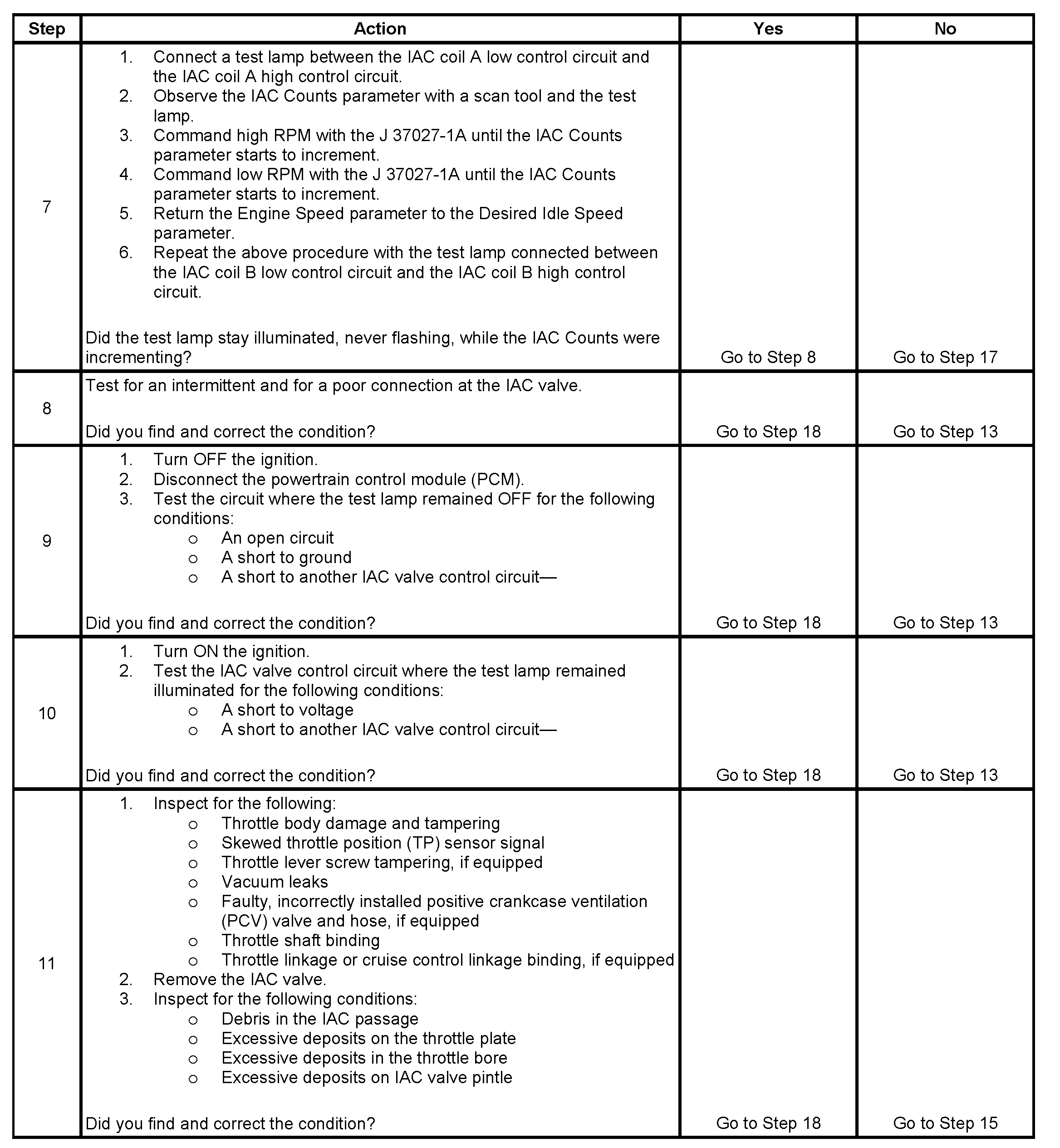
Steps 1 - 6
Picture 5
Steps 7 - 11
Picture 6
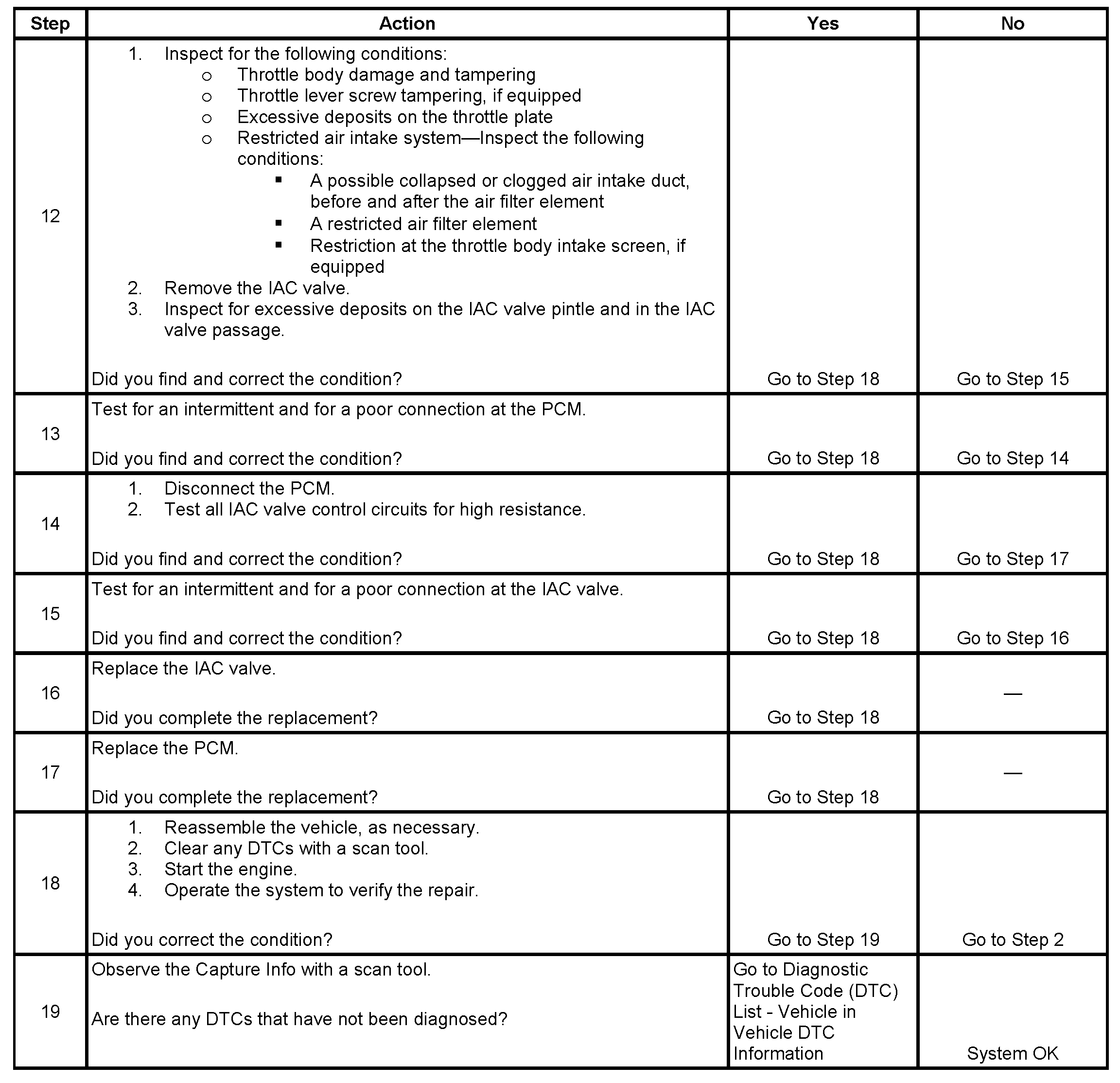
Steps 12 - 19
Pic 7
The numbers below refer to the step numbers on the diagnostic table.
5. This test will determine the ability of the PCM and IAC valve control circuits to control the IAC valve.
7. This test will determine the ability of the PCM to provide the IAC control valve circuits with a ground. On a normally operating system, the test lamp should not flash while the IAC Counts are incrementing.
__________________________________________
One last idea is related to the positive crankcase ventilation system (PCV). If there is a leak, which isn't uncommon on these hoses, it will cause the issue. I am going to provide the directions for removal and replacement of the PCV hoses. Use these directions to determine if anything is dry rotted, cracked, disconnected, or leaking. This should show up with a vacuum leak test.
________________________________________
Crankcase Ventilation Hoses/Pipes Replacement
Removal Procedure
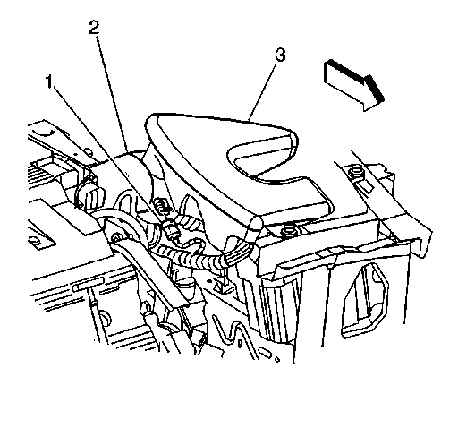
Picture 8
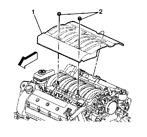
1. Remove the two nuts (2) from the fuel injector sight shield (1).
2. Lift the sight shield (1) from the front and pull forward to disengage the rear tab from the bracket.
Picture 9
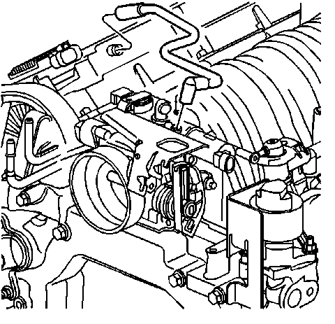
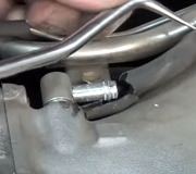
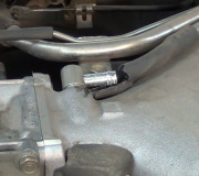
3. Disconnect the PCV fresh air tube from the left camshaft cover.
4. Remove the PCV fresh air tube from the throttle body.
5. Remove the drive belt.
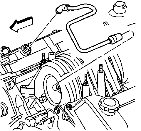
Picture 10
6. Remove the power steering pump retaining bolt.
7. With the hoses still attached, Carefully position aside the power steering pump.
Picture 11
8. Remove the retaining clip securing the PCV dirty air tube.
9. Disconnect the PCV dirty air tube from the PCV orifice tube.
10. Remove the PCV dirty air tube from the intake manifold.
Installation Procedure
Picture 12
1. Connect the PCV dirty air tube to the intake manifold fitting.
2. Connect the PCV dirty air tube to the PCV orifice tube.
Important: Ensure that the PCV dirty air tube is located between the tabs of the intake manifold.
3. Attach the retaining clip to the intake manifold.
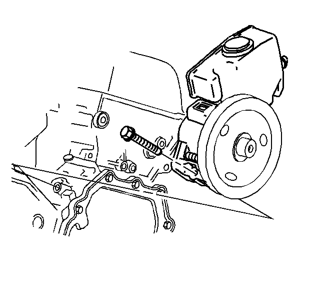
Picture 13
4. Place the power steering pump in position in the engine valley. Slide the molded wedge into the retaining feature cast into the cylinder block.
Notice: Refer to Fastener Notice in Service Precautions.
5. Install the power steering pump retaining bolt.
Tighten the power steering pump retaining bolt to 50 Nm (37 lb ft).
6. Install the drive belt.
Picture 14
7. Connect the PCV fresh air tube to the left camshaft cover.
8. Connect the PCV fresh air tube to the throttle body.
Picture 15
9. Align the rear tab with the slot in the rear bracket and push the sight shield (1) inward to engage.
10. Pull sight shield down and align the studs on the intake manifold with the holes in the sight shield (1).
11. Install the fuel injector sight shield nuts (2).
Tighten the fuel injector sight shield nuts to 3 Nm (27 lb in).
I realize this seems like a lot, but many of these tests only take a few minutest to complete.
Let me know what you find or if you find diagnostic trouble codes.
Take care,
Joe
Images (Click to make bigger)
Tuesday, February 26th, 2019 AT 5:02 PM