Welcome to 2CarPros.
I hope you are sitting down when you read this. Here are the directions for the entire control arm that is required to be removed to replaced the ball joint. All pictures attached correlate with the directions.
______________________________________
2001 Dodge Stratus Sedan L4-2.4L VIN X
Upper Control Arm
Vehicle Steering and Suspension Suspension Control Arm Service and Repair Procedures Rear Suspension Upper Control Arm
UPPER CONTROL ARM
REMOVAL
NOTE: The rear control arm, control arm bushings, and pivot bar are serviced as a complete assembly on this vehicle. Do not attempt to disassemble the control arm from the pivot bar to service the rear control arm bushings. The ball joint and ball joint seal are to be replaced with the control arm removed from the vehicle.
1. Raise vehicle on jackstands or centered on a frame contact type hoist.
2. Remove both rear wheel and tire assemblies from the vehicle.
pic 1
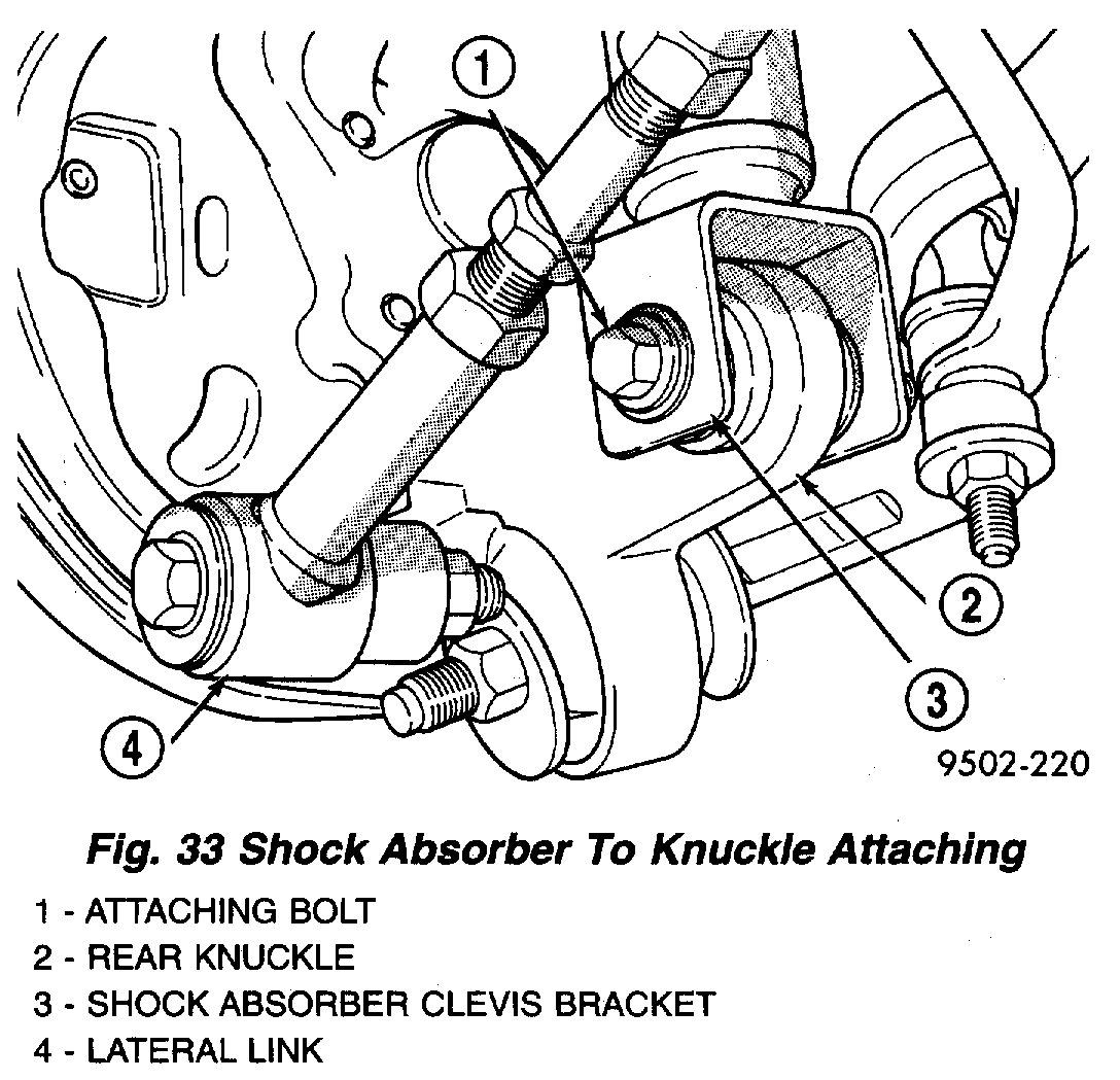
3. Remove the shock absorber clevis bracket to rear knuckle attaching bolt and nut on both sides of the vehicle.
pic 2
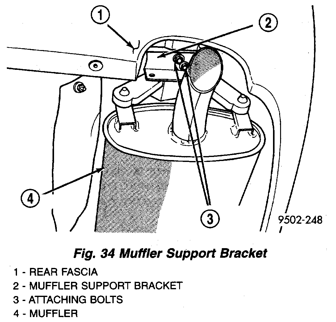
4. Remove muffler support bracket from rear frame rail.
pic 3
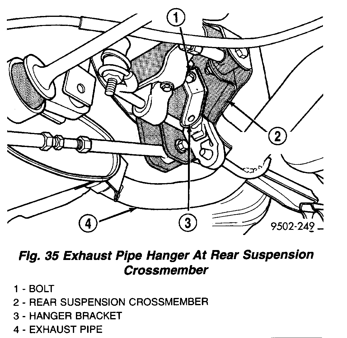
5. Remove the rear exhaust pipe hanger bracket from the rear suspension crossmember. Let exhaust system drop down as far as possible.
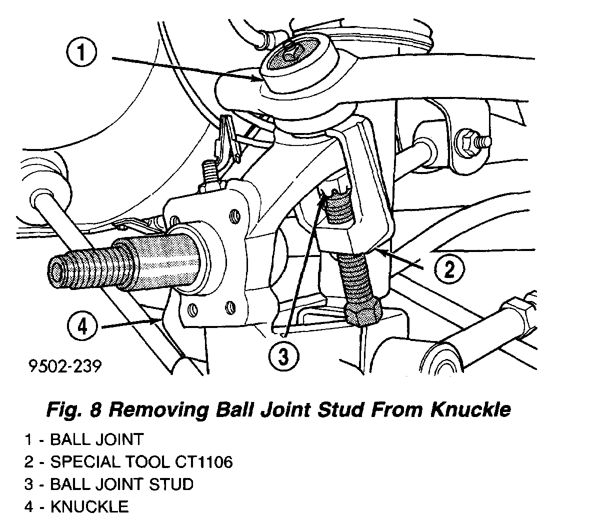
6. On only the side of the vehicle requiring control arm removal, separate the control arm ball joint from the rear knuckle using following procedure.
- Remove cotter pin and castle nut attaching upper control arm ball joint to knuckle.
pic 4
- Remove ball joint stud from knuckle using Puller, Special Tool, CT- 1106. When using puller, install castle nut on ball joint stud to protect threads from damage.
pic 5
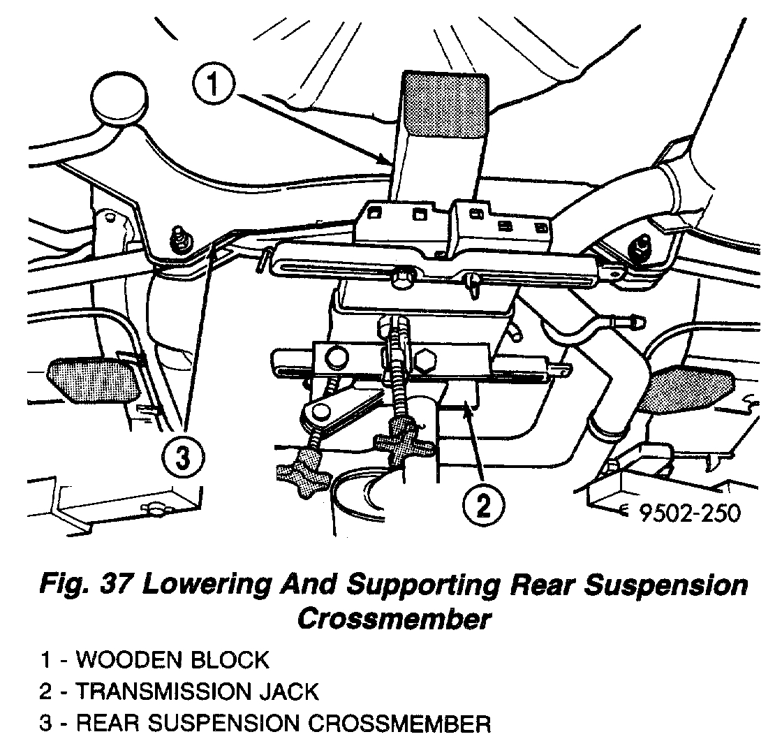
7. Position a transmission jack and wooden block under the center of the rear suspension crossmember to support and lower crossmember during removal.
pic 6
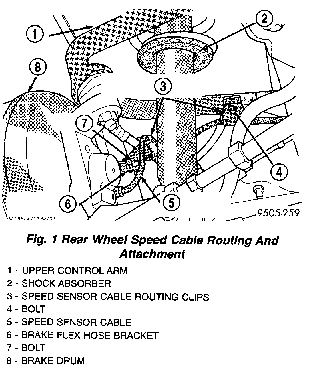
8. If vehicle is equipped with antilock brakes, remove routing clips for wheel speed sensor cable from brackets on both upper control arms.
pic 7
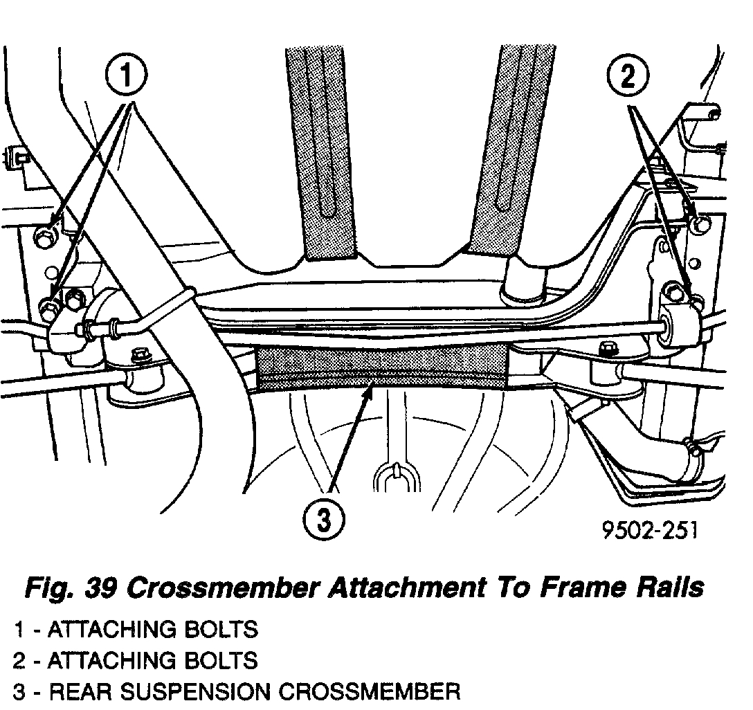
9. Remove the 4 bolts attaching rear suspension crossmember to rear frame rails.
CAUTION: When lowering rear suspension crossmember do not put a strain on the rear brake flex hoses.
10. Lower the rear suspension crossmember far enough to access the upper control arm pivot bar to crossmember attaching bolts.
NOTE: One flat washer is used at each upper control arm pivot bar attaching bolt. The flat washer is located between the pivot bar and the rear suspension crossmember. Be sure the washers are not lost when removing the pivot bar attaching bolts from the rear suspension crossmember.
pic 8
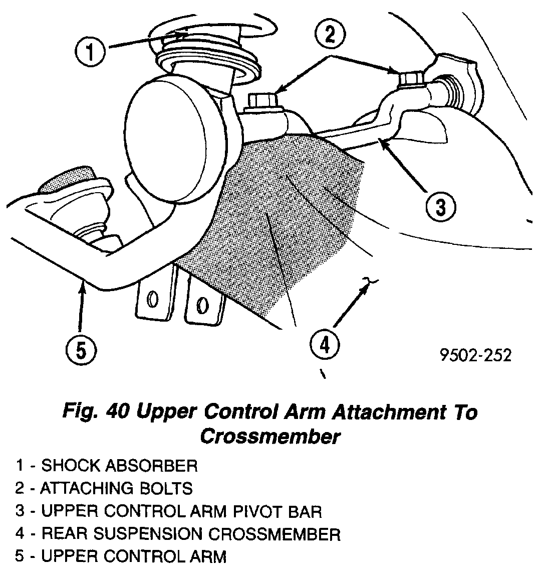
11. Remove the 2 bolts attaching the upper control arm to the rear suspension crossmember.
12. Remove the flat washers and the upper control arm from the rear suspension crossmember.
13. Transfer any required components to the replacement control arm.
DISASSEMBLY - UPPER BALL JOINT
The rear upper control arm must be removed from the vehicle for replacement of the ball joint.
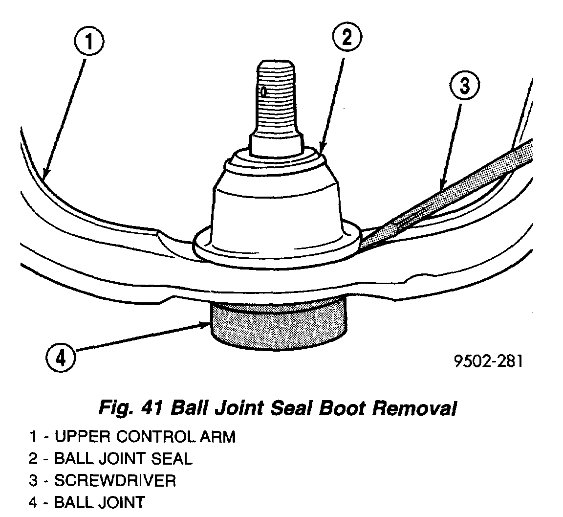
pic 9
1. Using a screw driver or other suitable tool, pry seal boot up and off of ball joint assembly.
pic 10
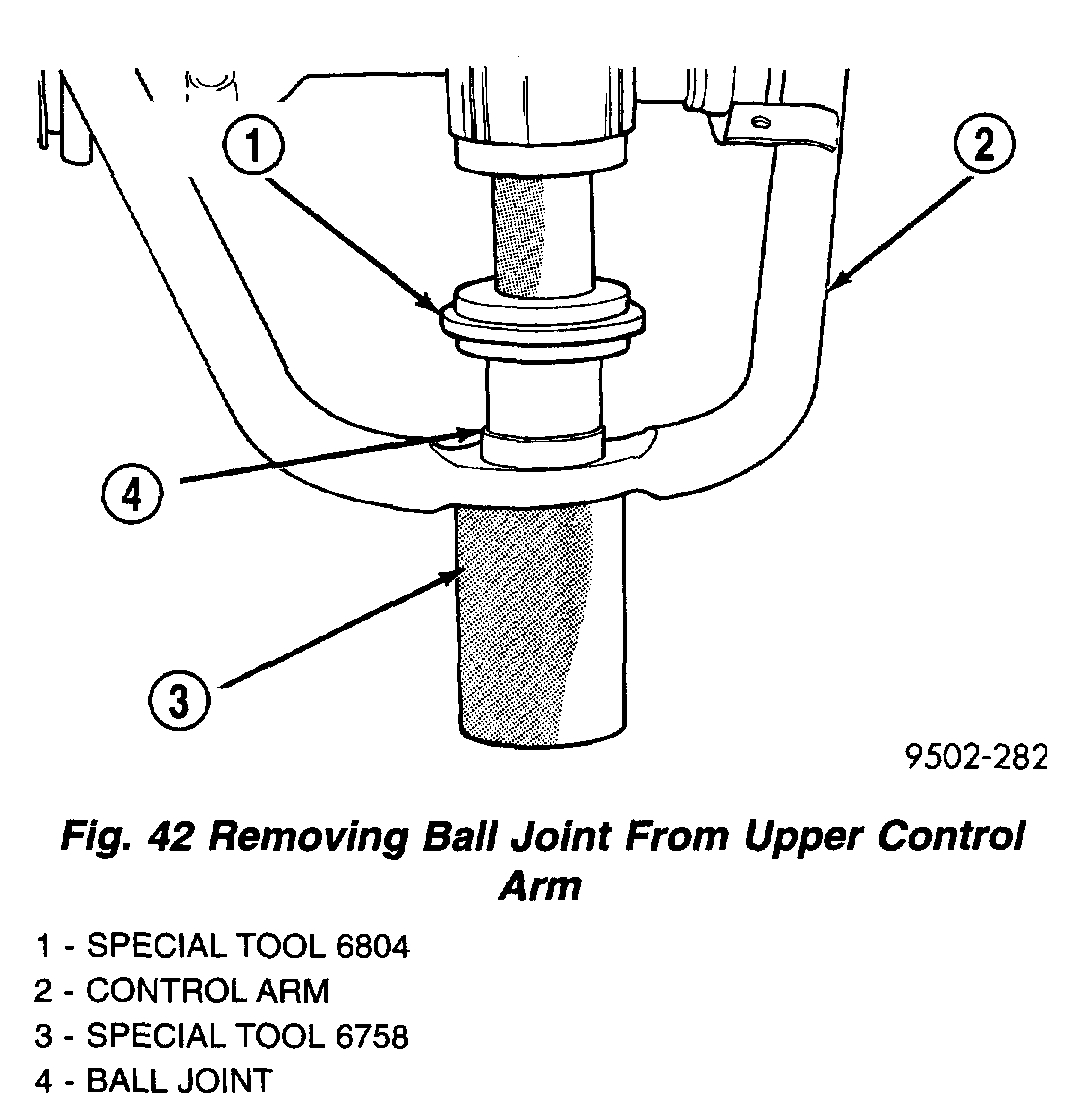
2. Position Receiving Cup, Special Tool 6758 to support control arm when removing ball joint assembly. Install Remover/Installer, Special Tool 6804 on top of ball joint assembly.
3. Using an arbor press, press the ball joint assembly out of the control arm.
INSPECTION
Inspect the control arm for physical damage. If it is determined that the upper control arm is broken or bent, the upper control arm must be replaced. The rear suspension upper control arm is not a repairable component and no attempt is to be made to repair or to straighten it. The upper control arm must be replaced if found to be damaged in any way.
Inspect the control arm pivot bushings for deterioration. If found to need replacement, the upper control arm is to be replaced.
The rear control arm, control arm bushings, and pivot bar are serviced as a complete assembly on this vehicle. Do not attempt to disassemble the control arm from the pivot bar to service the rear control arm bushings.
The only component on the upper control arm that is serviceable is the rear upper ball joint and its seal.
ASSEMBLY - UPPER BALL JOINT
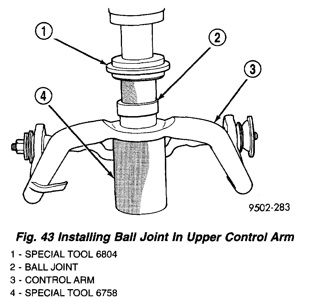
1. By hand, position ball joint assembly into ball joint bore of control arm. Be sure ball joint assembly is not cocked in the bore of the control arm, this will cause binding of the ball joint assembly, when being pressed into lower control arm.
pic 11
2. Position assembly in an arbor press with Receiving Cup, Special Tool 6758 supporting lower control arm. Then install Remover/Installer, Special Tool 6804 on the top of the ball joint assembly.
CAUTION: When installing the ball joint in the upper control arm, do not press the ball joint into the control arm all the way. The lip on the ball joint must not touch the surface of the control arm. Refer to Step 3 below when installing the ball joint.
3. Carefully align all pieces. Using the arbor press, press the ball joint into the control arm until a gap of 3 mm (1/8 inch) is between lip on ball joint and surface of lower control arm.
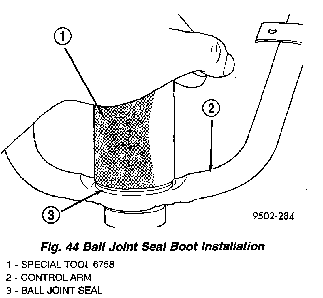
4. Install a NEW ball joint assembly sealing boot on ball joint assembly.
CAUTION: Do not use an arbor press to install the sealing boot on the lower control arm ball joint assembly. Damage to the sealing boot can occur due to excessive pressure applied to sealing boot when being installed.
pic 12
5. Position Receiving Cup, Special Tool 6758 over sealing boot so it is aligned properly with bottom edge of sealing boot. Apply pressure BY HAND to special tool 6768, until sealing boot is pressed squarely against surface of control arm.
6. Reinstall the control arm on the vehicle.
INSTALLATION
NOTE: The rear control arm, control arm bushings, and pivot bar are serviced as a complete assembly on this vehicle. Do not attempt to disassemble the control am, from the pivot bar to service the rear control arm bushings. The ball joint and ball joint seal are to be replaced with the control arm removed from the vehicle.
NOTE: One flat washer is used at each upper control arm pivot bar attaching bolt. The flat washer is located between the pivot bar and the rear suspension crossmember. Be sure 1 flat washer is used at each bolt attaching the pivot bar to the rear suspension crossmember.
1. Align the upper control arm pivot bar with the mounting holes in the rear suspension crossmember. Install the pivot bar attaching bolts and washers. Tighten the 2 pivot bar to crossmember attaching bolts to a torque of 108 Nm (80 ft. lbs.).
2. Using transmission jack, raise rear suspension crossmember up to the rear frame rails and loosely install the 4 attaching bolts.
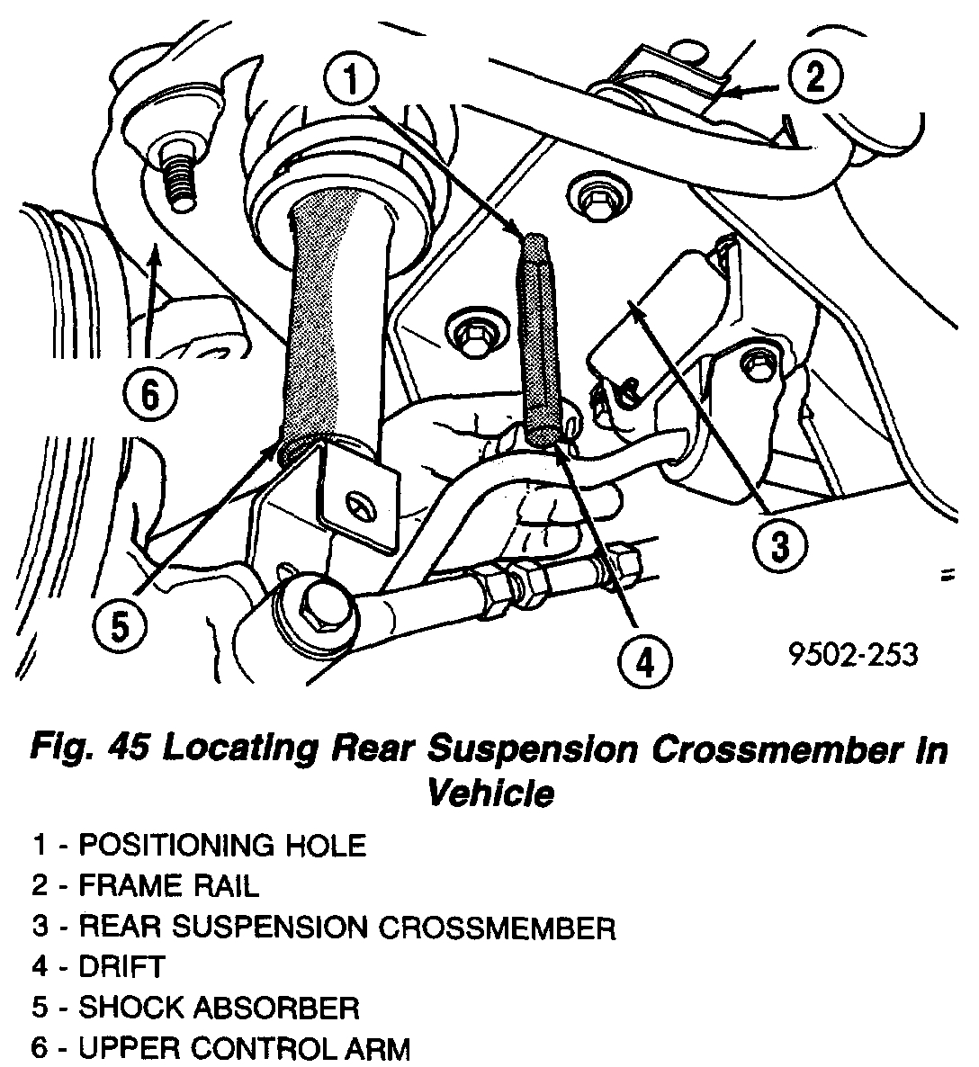
pic 13
3. Position an appropriate size drift into the positioning hole in each side of rear suspension crossmember and crossmember locating holes in frame rails of the vehicle. This is required to properly position rear suspension crossmember in the body of the vehicle. Then tighten the 4 crossmember to frame rail attaching bolts to 108 Nm (80 ft. lbs.). Remove drifts from rear suspension crossmember.
4. Install upper ball joint stud in knuckle. Install and tighten the ball joint stud castle nut to a torque of 85 Nm (63 ft. lbs.). Install cotter pin in ball joint stud.
5. Remove transmission jack supporting rear suspension crossmember.
6. Install muffler support bracket on rear frame rail. Install rear exhaust pipe hanger on rear suspension crossmember.
7. Install the wheel speed sensor cable routing clip on upper control arm mounting bracket. Install and securely tighten attaching bolt.
8. Install the shock absorber clevis brackets on the rear knuckles. Tighten the shock absorber mounting bolts to a torque of 95 Nm (70 ft. lbs.).
9. Install wheel and tire assembly on vehicle. Tighten the wheel mounting stud nuts in proper sequence until all nuts are torqued to half specification. Then repeat the tightening sequence to the full specified torque of 135 Nm (100 ft. lbs.).
10. Lower vehicle to the ground.
11. Check and reset if required, rear wheel Camber and Toe to preferred specifications.
__________________________
Let me know if this is what you needed.
Take care,
Joe
Images (Click to enlarge)
Oct 2, 2019 at 4:38 PM