Required no tweaking. Made the pin adjustments as we discussed and SMOOTH sailing from there.
Just took my time checking, re-checking & triple checking all of the connections.
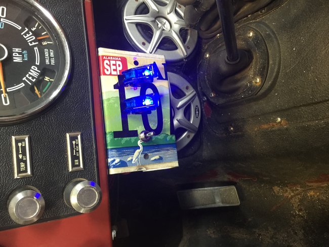
Plugged her in and she fired right up!!!
Thinking I need to label these safety toggles. Maybe "MASTER ARM" and "EJECT"
Sep 30, 2016 at 5:50 AM