Hello,
for the fault code p2135 and p1295, p2106 related to each other.
GENERAL DESCRIPTION
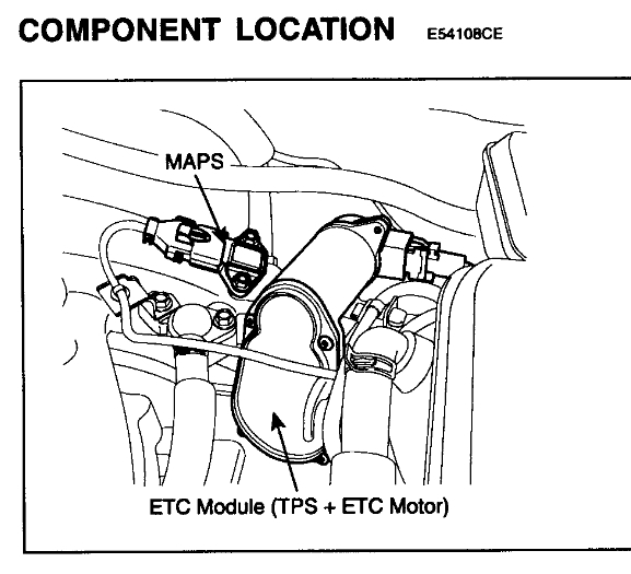
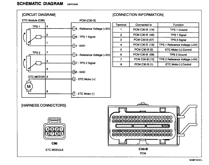
The Electronic Throttle Control (ETC) system is made of the components throttle body, Throttle Position Sensor (TPS) 1 & 2 and Accelerator Position Sensor (APS) 1 & 2. TPS 1 & 2 are sharing the same source voltage and ground The throttle valve opening is control by throttle motor which is controlled by Engine Control Module (ECM). The opposite position indicator shows inverted signal characteristics. TPS 1 output voltage increases smoothly in proportion with the throttle valve opening angle after starting. TPS 2 output voltage decreases in inverse proportion with the throttle valve opening angle after starting. TPS provides feedback to the ECM to control the throttle motor in order to control the throttle valve opening angle properly in response to the driving condition.(check pic1)
DTC DESCRIPTION
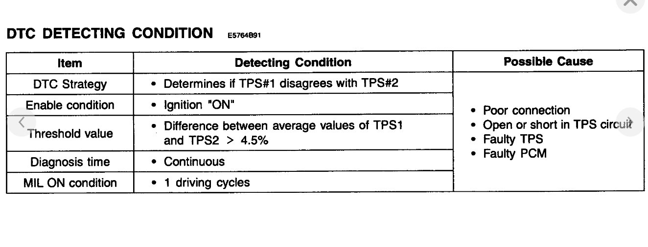
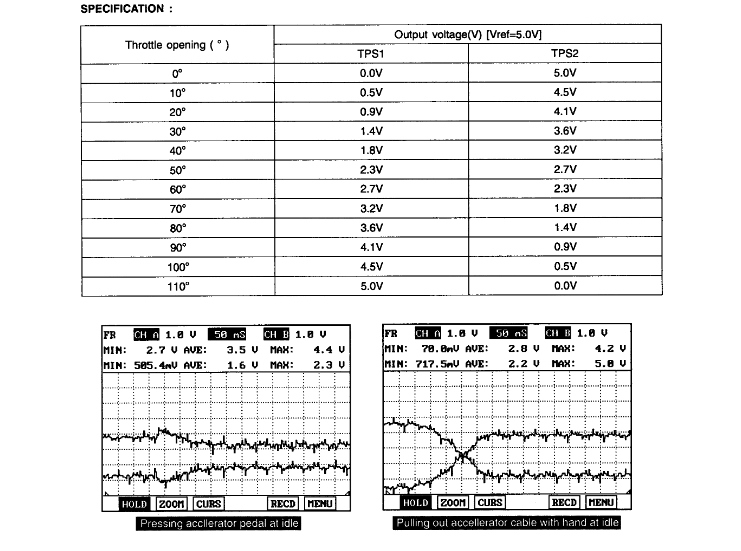
Checking output signals from TPS 1 and 2 under detecting condition, if output signals difference between TPS 1 and TP S2 are detected more than 4.5% for the specified number of times., PCM sets P2135. And then MIL (Malfunction Indication Lamp) turns on.(check pic2)
MONITOR DTC STATUS
1. Check DTC Status
1. Connect scantool to Data Link Connector (DLC).
2. IG "ON".
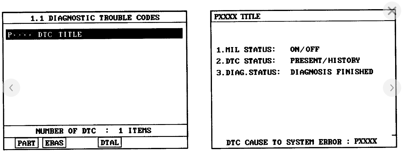
3. Select "Diagnostic Trouble Codes (DTCs)" mode, and then Press F4 (DTAL) to check DTC's information from the DTCs menu
4. Read "DTC Status" parameter.(checkpic3)
5. Is parameter displayed "Present fault"?
YES - Go to "Terminal and connector inspection" procedure.
NO - Fault is intermittent caused by poor contact in the sensor's and/or PCM's connector or was repaired and PCM memory was not cleared. Thoroughly check connectors for looseness, poor connection, ending, corrosion, contamination, deterioration, or damage. Repair or replace as necessary and go to "Verification of Vehicle Repair" procedure.
TERMINAL AND CONNECTOR INSPECTION
1. Many malfunctions in the electrical system are caused by poor harness and terminals. Faults can also be caused by interference from other electrical systems, and mechanical or chemical damage.
2. Thoroughly check connectors for looseness, poor connection, bending, corrosion, contamination, deterioration, or damage.
3. Has a problem been found?
YES - Repair as necessary and go to "Verification of Vehicle Repair" procedure.
NO - Go to "Power Circuit Inspection" procedure.
POWER CIRCUIT INSPECTION(pic4)
1. IG "OFF".
2. Disconnect TPS connector.
3. IG "ON" & ENG "OFF".
4. Measure voltage between terminal 4 of TPS harness connector and chassis ground.
5. Measure voltage between terminal 7 of TPS harness connector and chassis ground.
Specification : Approx. 5 V
6. Is the measured voltage within specification ?
YES - Go to "Signal Circuit Inspection" procedure.
NO - Repair or replace as necessary and then, go to "Verification of Vehicle Repair" procedure.
SIGNAL CIRCUIT INSPECTION
1. IG "OFF".
2. Disconnect TPS & PCM connector.
3. Measure resistance between terminal 2 and 3 of TPS harness connector.
Specification : Infinite
4. Is the measured resistance within specification ?
YES - Go to "Component Inspection" procedure.
NO - Repair or replace as necessary and then, go to "Verification of Vehicle Repair" procedure.
COMPONENT INSPECTION(pic5)
1. Check TPS
1. Ignition "ON" & ENG "OFF".
2. Monitor signal waveform of TPS by stepping on and oft the accelerator pedal on scantool
3. Is the measured signal waveform O.K?
YES - Substitute with a known-good PCM and check for proper operation. If the problem is corrected, replace PCM and then go to "Verification of Vehicle Repair" procedure.
NOTE: There is a memory reset function on scantool that can erase optional parts automatically detected and memorized by PCM.
Before or after testing PCM on the vehicle, use this function to reuse the PCM on the others.
NO - Substitute with a known-good TPS and check for proper operation. If the problem is corrected, replace TPS and then go to "Verification of Vehicle Repair" procedure.
(After replacing ETC, do initialization of ETC as follows)
PROCEDURE OF ETS INITIALIZATION
1. Erase the trouble codes on PCM
2. Turn the ignition key off and keep this condition until the main relay is turned off. (It will takes 10 sec.)
3. Turn ignition key on more than 1 second to record the throttle motor position on the EEPROM
VERIFICATION OF VEHICLE REPAIR
After a repair, it is essential to verify that the fault has been corrected.
1. Connect scan tool and select "Diagnostic Trouble Codes (DTCs)" mode
2. Press F4 (DTAL) and confirm that "DTC Readiness Flag" indicates "Complete". If not, drive the vehicle within conditions noted in the freeze frame data or enable conditions
3. Read "DTC Status" parameter
4. Is parameter displayed "History (Not Present) fault"?
YES - System performing to specification at this time. Clear the DTC.
NO - Go to the applicable troubleshooting procedure.
for the fault code p0638.
DTC DESCRIPTION
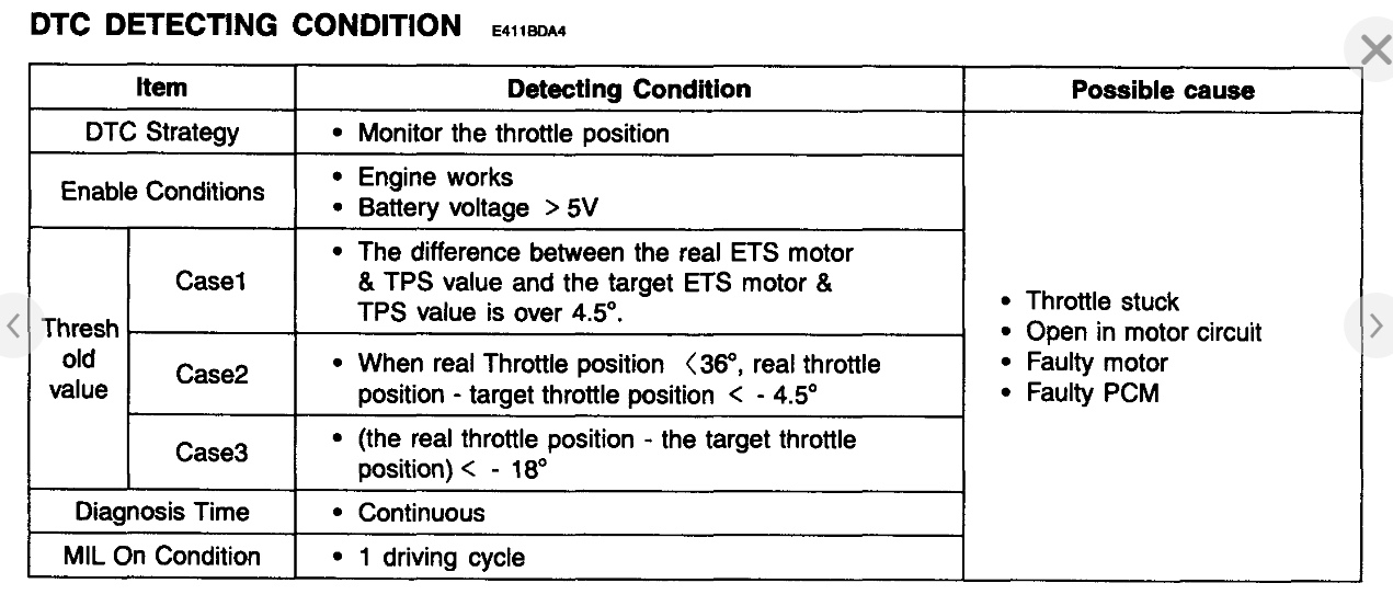
Checking output signals from TPS under detecting condition, if the difference between real and target throttle position is above the specified value, PCM sets P0638 and then MIL (Malfunction Indication Lamp) turns on.(pic6)
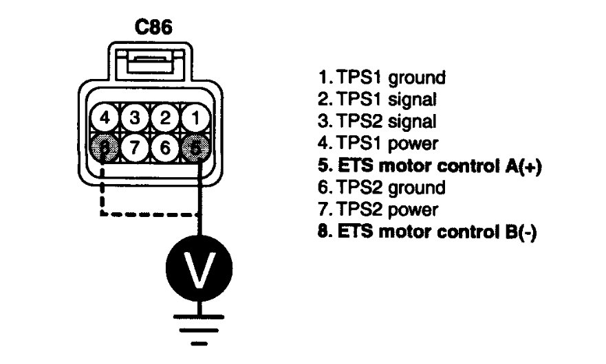
CONTROL CIRCUIT INSPECTION(pic7)
1. Check voltage
1. IG "OFF".
2. Disconnect ETS motor & TPS connector.
3. IG "ON" and ENG "OFF"
4. Measure the voltage between terminal 5, 8 of ETS motor & TPS harness connector and chassis ground.
Specification : Approx. 12 V
5. Is the measured voltage within specification?
YES - Go to "Component inspection" procedure.
NO - Go to "Check open in harness" as follows.
2. Check open in harness(pic8)
1. IG "OFF"
2. Disconnect ETS motor & TPS connector and PCM connector.
3. Measure the resistance between terminal 5 of ETS motor & TPS harness connector and terminal 2 of PCM harness connector.
4. Measure the resistance between terminal 8 of ETS motor & TPS harness connector and terminal 1 of PCM harness connector.
Specification : Approx. below 1 ohm
5. Is the measured resistance within specification ?
YES - Go to "Component inspection" procedure.
NO - Repair Open in motor harness and go to "Verification of Vehicle Repair" procedure.
COMPONENT INSPECTION
1. Check throttle valve for stuck
1. IG "OFF".
2. Disconnect the air hose between throttle body and air mass flow sensor.
3. Check stuck on throttle valve.
4. Is the throttle valve normal?
YES - Go to check "ETS motor resistance" as follows.
NO - Repair or replace as necessary and go to "Verification of Vehicle Repair" procedure.
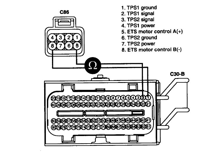
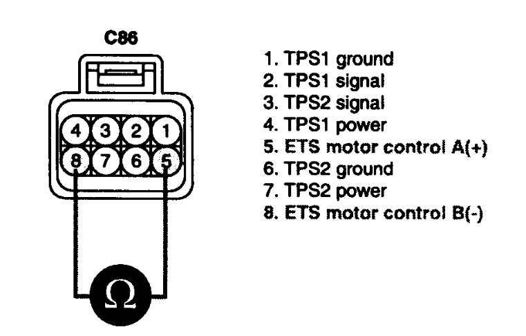
2. Check ETS motor resistance(pic9)
1. IG "OFF".
2. Disconnect ETS motor & TPS connector.
3. Measure the resistance between terminal 5 and 8 of ETS motor & TPS connector (component side).
Specification : Approx. 1.275 - 1.725 ohms @ 23 °C (73.4 °F)
4. Is the measured resistance within specification?
YES - Go to "ETC motor actuation test" procedure.
NO - Substitute with a known - good ETC motor and check for proper operation. If the problem is corrected, replace ETC motor and go to "Verification of Vehicle Repair" procedure.
Procedure of ETS Initialization
1. Erase the trouble codes on PCM
2. Turn the ignition key off and keep this condition until the main relay is turned off. (It will takes 10 second)
3. Turn ignition key on more than 1 second to record the throttle motor position on the EEPROM
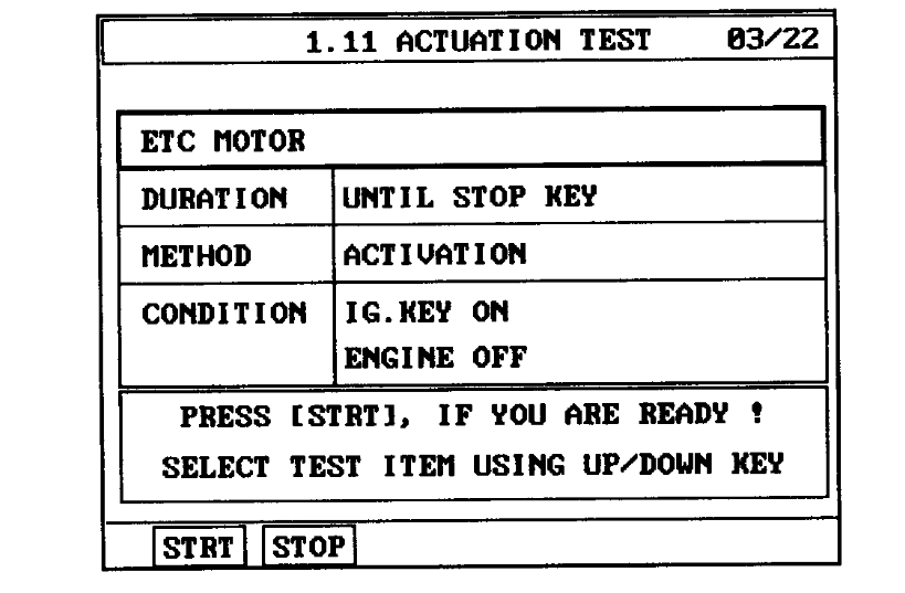
3. ETC motor actuation test(pic10)
1. IG "OFF".
2. Connect ETS motor & TPS connector.
3. After IG "ON", execute the "ETC motor actuation test" by Scantool.
4. Does the "ETC motor actuation test" execute normally?
YES - Substitute with a known - good PCM and check for proper operation. If the problem is corrected, replace PCM and go to "Verification of Vehicle Repair" procedure.
NO - Substitute with a known - good ETC motor and check for proper operation. If the problem is corrected, replace ETC motor and go to "Verification of Vehicle Repair" procedure.
Procedure of ETS Initialization
1. Erase the trouble codes on PCM
2. Turn the ignition key off and keep this condition until the main relay is turned off. (It will takes 10 second)
3. Turn ignition key on more than 1 second to record the throttle motor position on the EEPROM
VERIFICATION OF VEHICLE REPAIR
After a repair, it is essential to verify that the fault has been corrected.
1. Connect scan tool and select "Diagnostic Trouble Codes (DTCs)" mode
2. Press F4 (DTAL) and confirm that "DTC Readiness Flag" indicates "Complete". If not, drive the vehicle within conditions noted in the freeze frame data or enable conditions
3. Read "DTC Status" parameter
4. Is parameter displayed "History (Not Present) fault"?
YES - System performing to specification at this time. Clear the DTC.
NO - Go to the applicable troubleshooting procedure.
thank u ,please lets us know what happens with you.
Images (Click to enlarge)
Feb 1, 2019 at 10:29 AM