Hi,
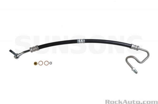
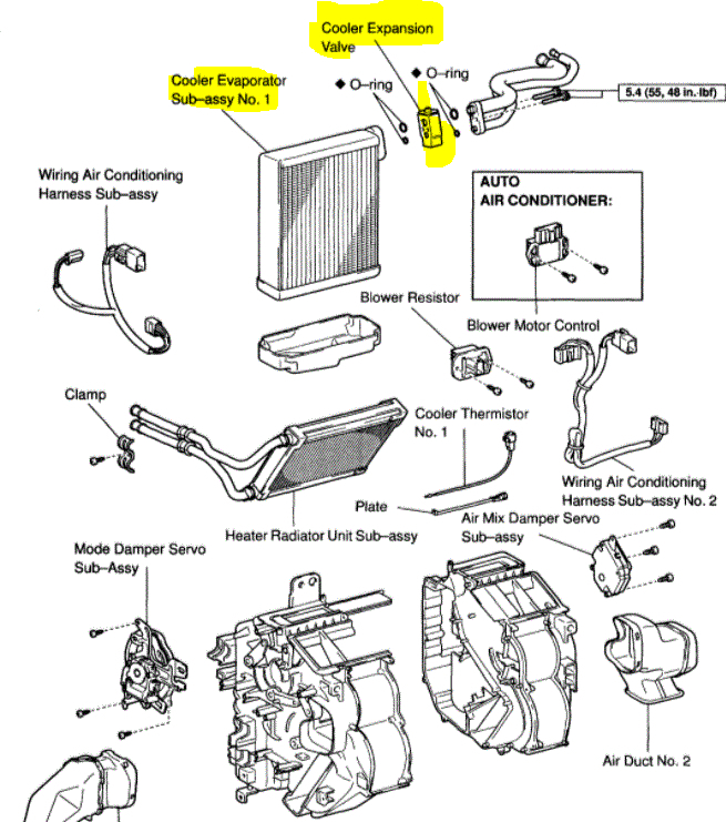
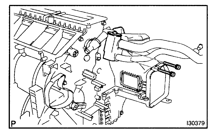
The evaporator and expansion valve are under the dash and take a lot of work to access. If you look at pic 1, it shows the two components.
____________________________
Here are the directions to remove and replace.
2003 Toyota Truck Highlander 2WD L4-2.4L (2AZ-FE)
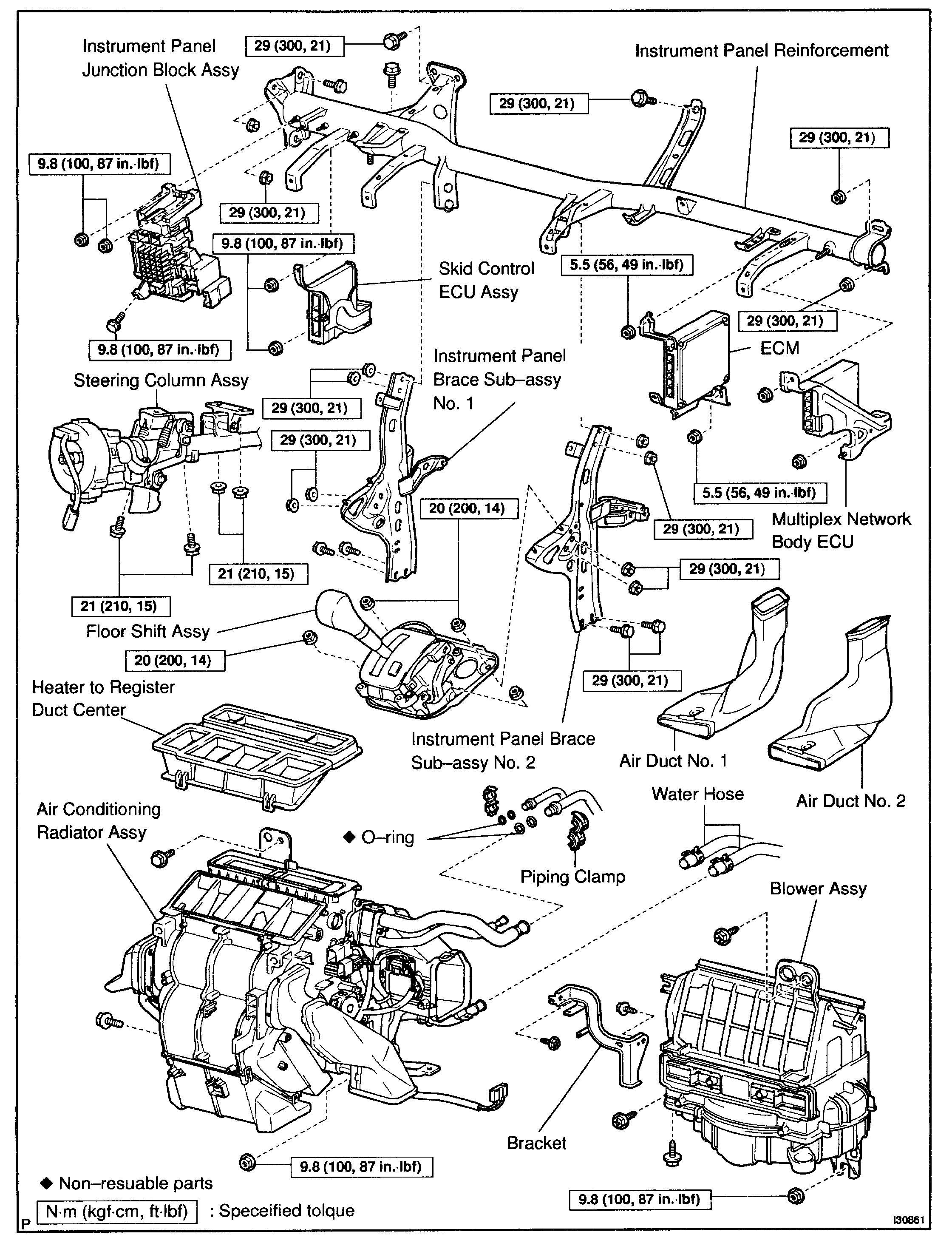
Air Conditioning Radiator Assy
Vehicle Heating and Air Conditioning Evaporator Case Service and Repair Procedures Air Conditioning Radiator Assy
AIR CONDITIONING RADIATOR ASSY
Heater And Air Conditioner
pic 2
Heater And Air Conditioner
pic 3
Heater & Air Conditioner
pic 4
Heater & Air Conditioner
pic 5
OVERHAUL
1. DRAIN HFC-134A (R134A)
pic 6
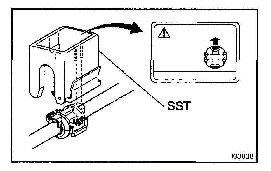
2. SEPARATE COOLER REFRIGERANT SUCTION PIPE NO.1
a. Install SST to piping clamp.
SST 09870-00015
HINT: Confirm the direction of the piping clamp claw and SST using the illustration showing on the caution label.
Pic 7
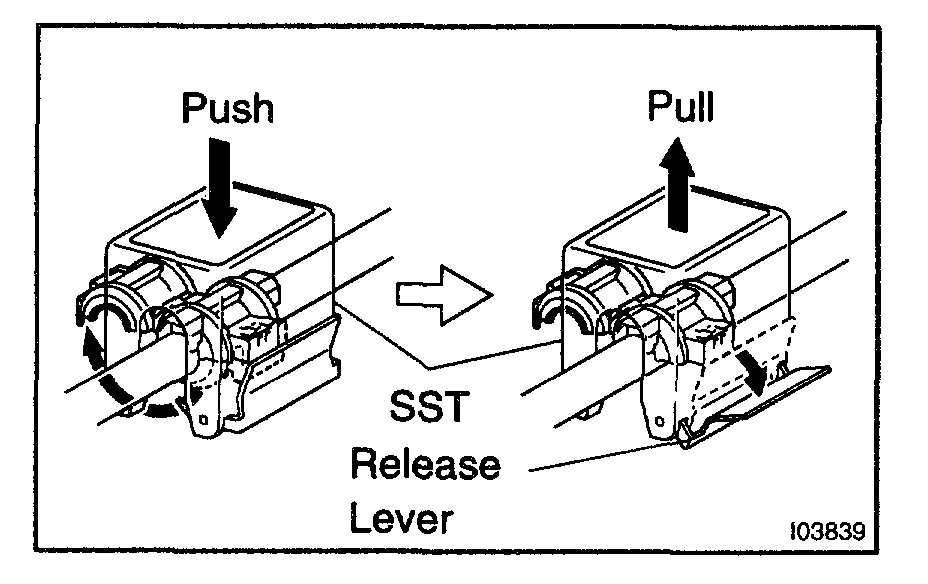
b. Push down the SST and release the clamp lock.
NOTE: Be careful not to deform the tube, when pushing SST.
C. Pull SST slightly and push the release lever, then remove the piping clamp with SST.
Pic 8
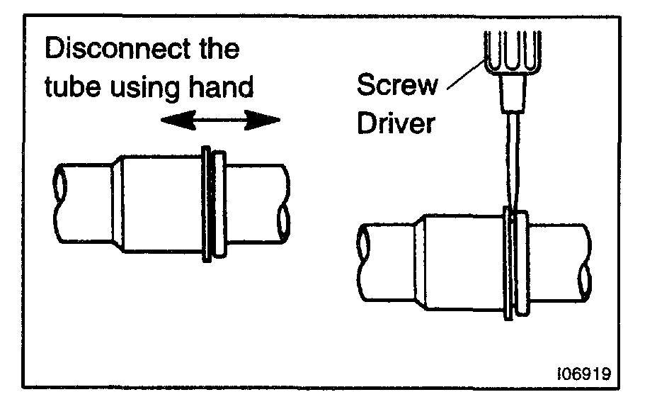
d. Disconnect the cooler refrigerant suction hose No.1.
NOTE:
- Do not use tools like screwdriver to remove the tube.
- Cap the open fittings immediately to keep moisture or dirt out of the system.
3. SEPARATE COOLER REFRIGERANT LIQUID PIPE A
a. Disconnect in the same way as the cooler refrigerant suction hose No.1.
SST 09870-00025
pic 9
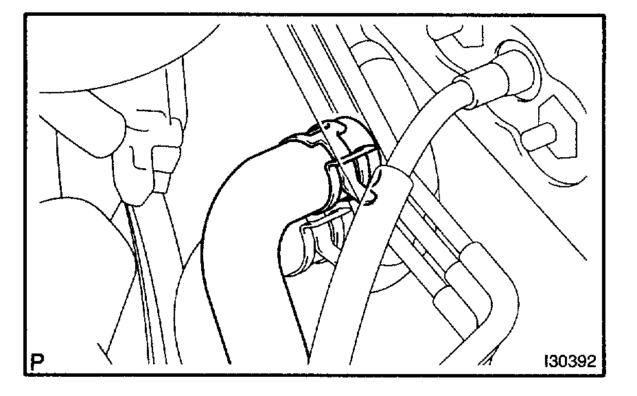
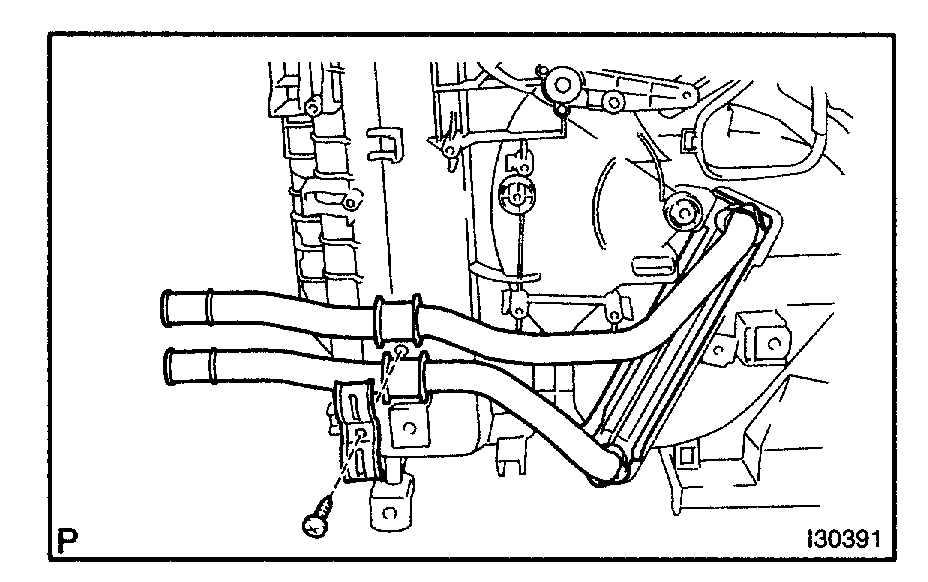
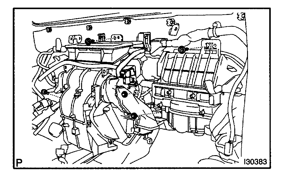
4. SEPARATE HEATER OUTLET WATER HOSE
a. Slide the clip and disconnect the heater outlet water hose.
5. SEPARATE HEATER INLET WATER HOSE
a. Slide the clip and disconnect the heater inlet water hose.
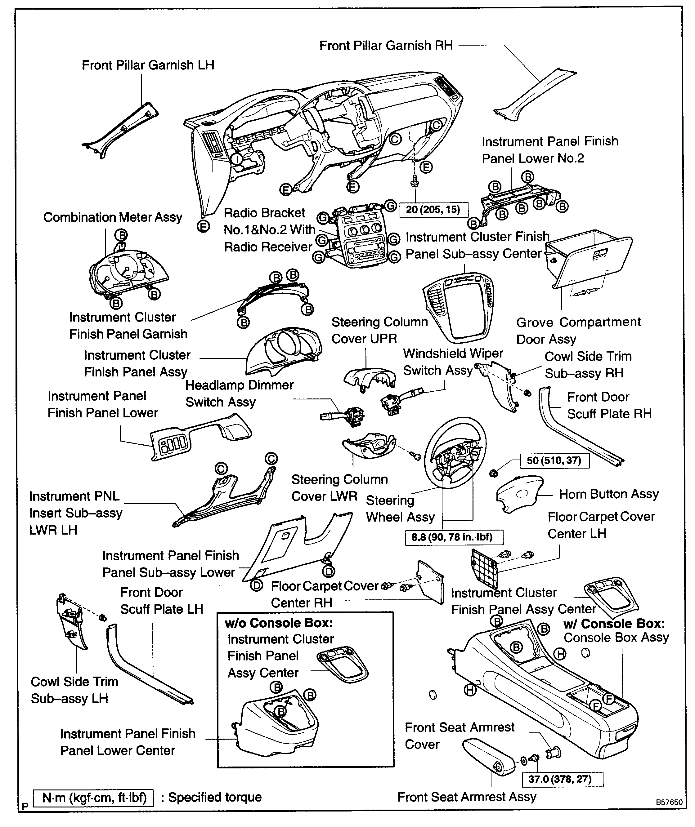
6. REMOVE INSTRUMENT PANEL SAFETY PAD SUB-ASSY
SST 09950-50013 (09951-05010, 09952-05010, 09953-O5020, 09954-05021)
HINT: Refer to the instructions for removal of the instrument panel safety pad sub-assy.
Pic 10
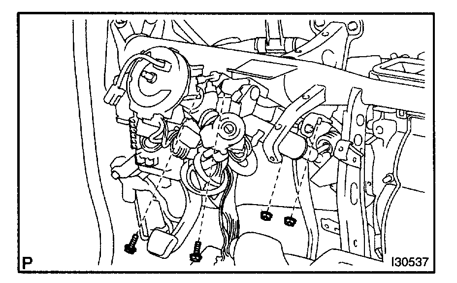
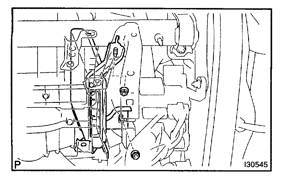
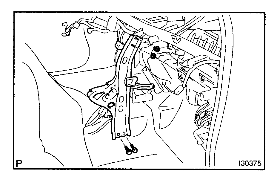
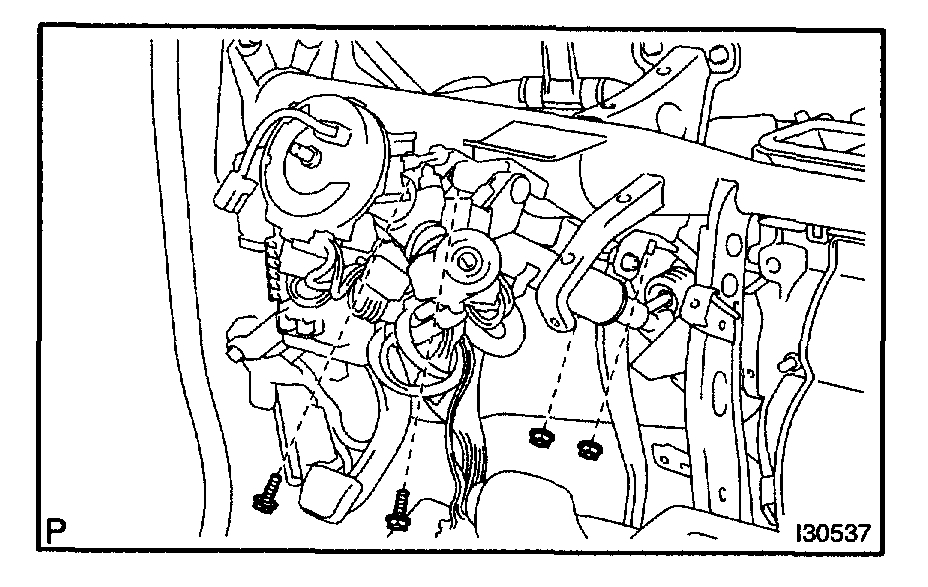
7. SEPARATE STEERING COLUMN ASSY
a. Remove the 2 bolts and 2 nuts, disconnect the steering column assy from the instrument panel reinforcement assy.
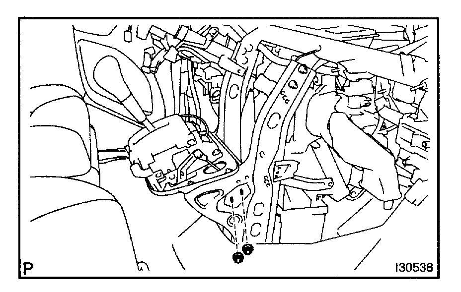
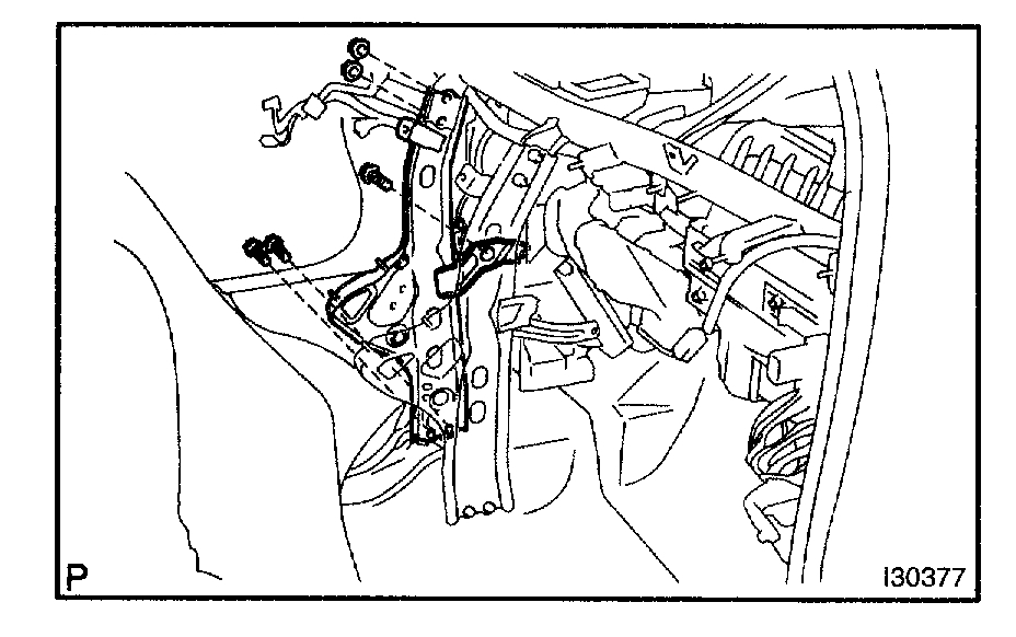
8. SEPARATE FLOOR SHIFT ASSY
pic 11
a. Remove the 2 nuts and disconnect the shift cable.
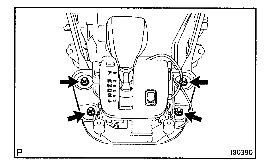
Pic 12
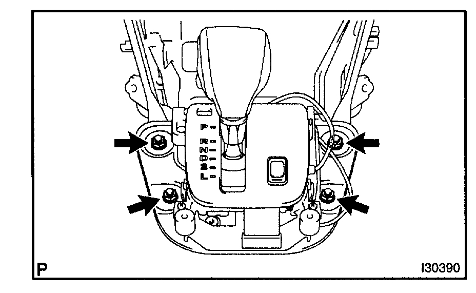
b. Remove the 4 nuts and disconnect transmission floor shift assy.
Pic 13
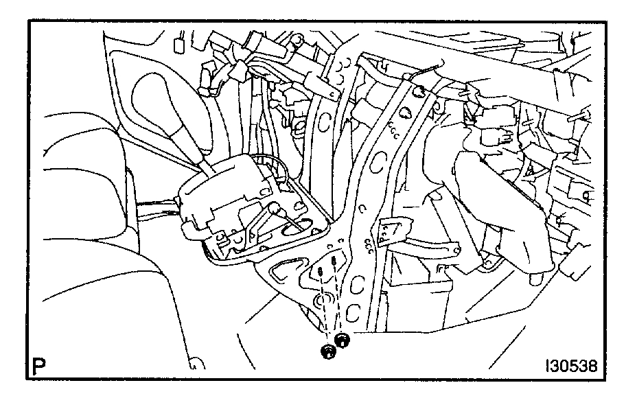
9. REMOVE AIR DUCT REAR NO.2
a. Remove the side scuff plate.
B. Remove the floor carpet.
HINT: Turn up the floor carpet to a certain extent so that the air duct rear No.2 can be remove.
C. Remove the air duct rear No.2.
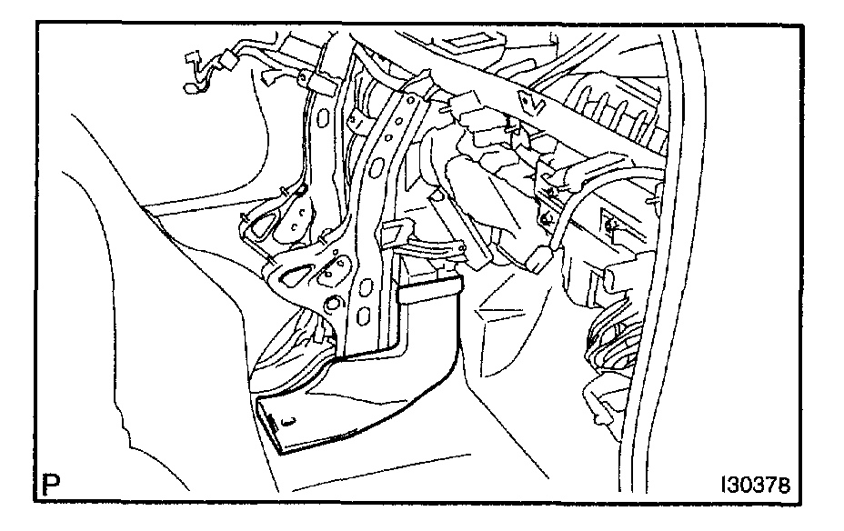
10. REMOVE AIR DUCT REAR NO.1
HINT: Remove it in the same way with the air duct rear No.2.
Pic 14
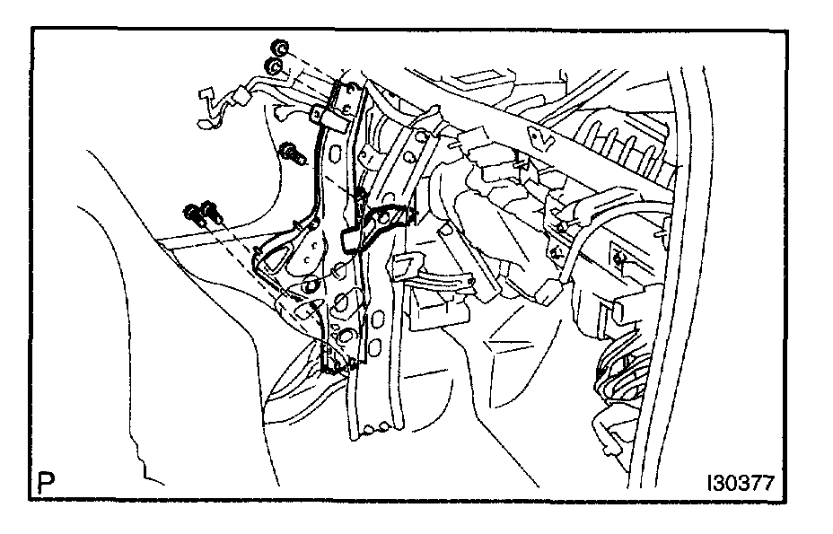
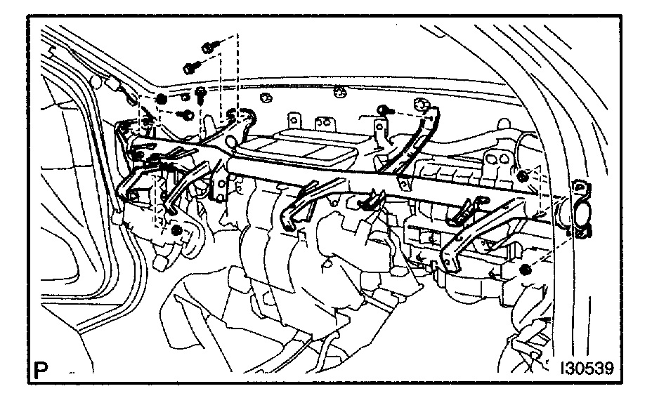
11. REMOVE INSTRUMENT PANEL BRACE SUB-ASSY NO.1
a. Disconnect the connector clamp.
B. Remove the 3 bolts, 2 nuts and instrument panel brace sub-assy No.1.
Pic 15
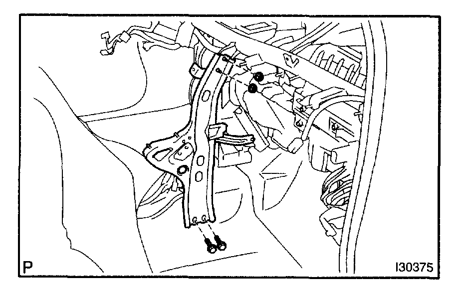
12. REMOVE INSTRUMENT PANEL BRACE SUB-ASSY NO.2
a. Remove the 2 bolts, 2 nuts and instrument panel brace SUB-Assy No.2.
Pic 16
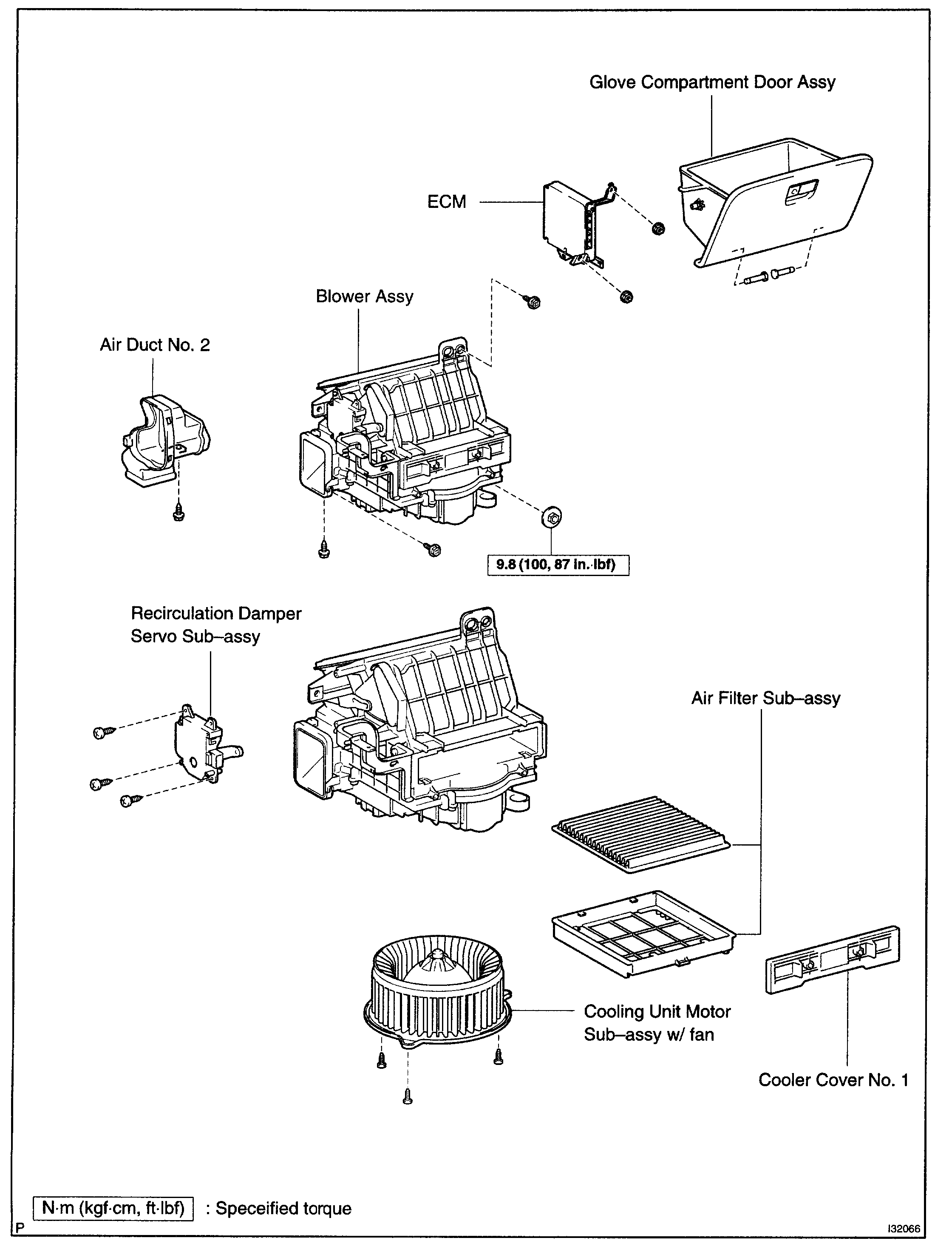
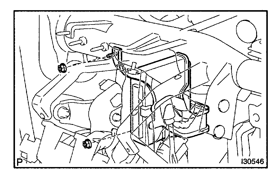
13. SEPARATE ECM
a. Remove the 2 nuts, disconnect the ECM.
Pic 17
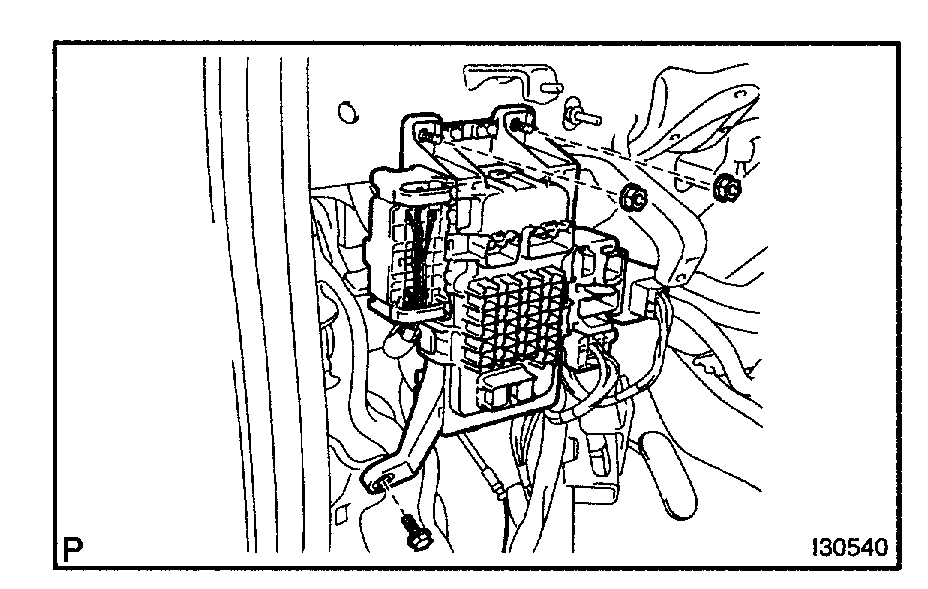
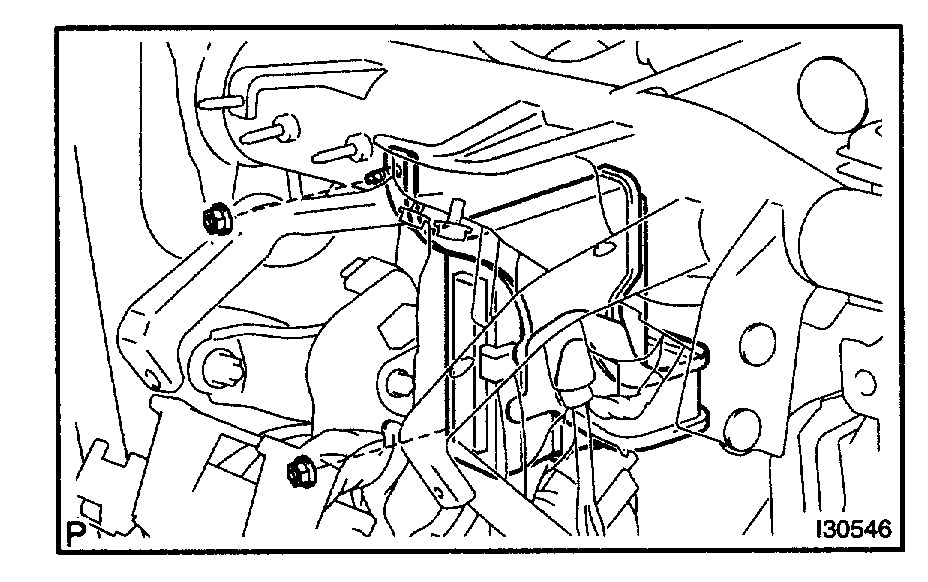
14. SEPARATE MULTIPLEX NETWORK BODY ECU
a. Remove the 2 nuts and multiplex network body ECU.
Pic 18
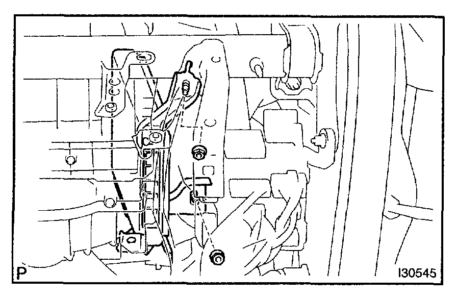
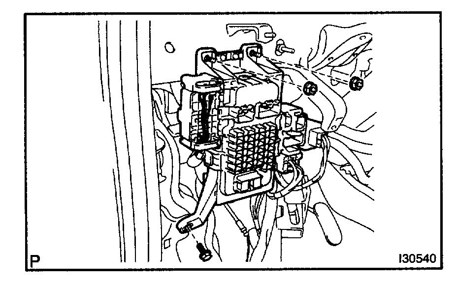
15. SEPARATE INSTRUMENT PANEL JUNCTION BLOCK ASSY
a. Remove the bolt and 2 nuts, disconnect the instrument panel junction block assy.
Pic 19
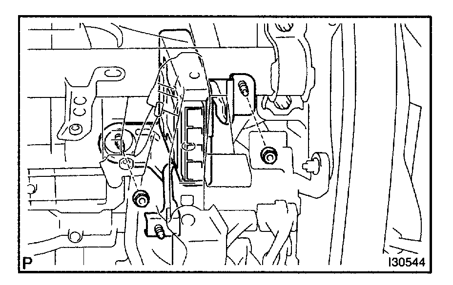
16. SEPARATE SKID CONTROL ECU ASSY
a. Remove the 2 nuts and disconnect the skid control ECU assy.
Pic 20
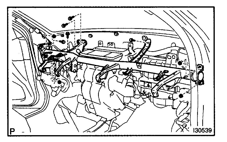
17. REMOVE INSTRUMENT PANEL REINFORCEMENT ASSY
a. Remove the 5 bolts, 4 nuts and instrument reinforcement assy.
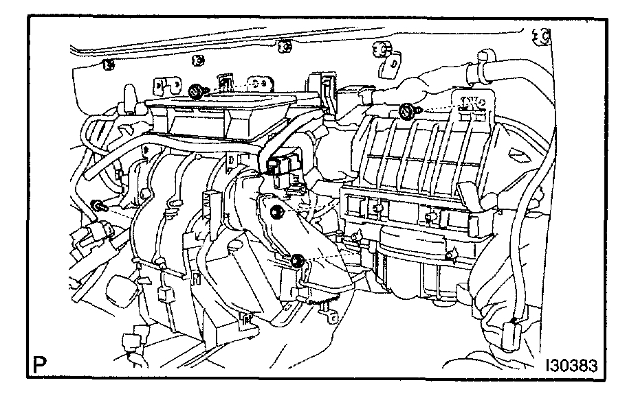
18. REMOVE AIR CONDITIONER UNIT ASSY
pic 21
a. Disconnect the connector and clamp.
Pic 22
b. Disconnect the connectors connecting the wiring air indicator harness sub-assy and vehicle harness.
C. Remove the 3 bolts, 2 nuts and air conditioner unit assy.
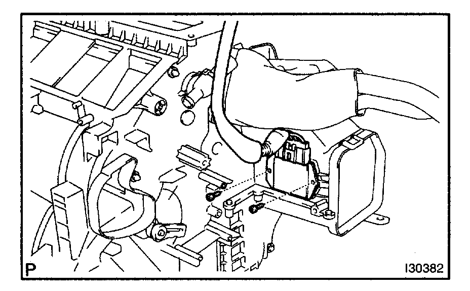
19. REMOVE AIR CONDITIONING RADIATOR ASSY
a. Remove the screw, disconnect the connected part of the duct and take off the air duct No.2.
Pic 23
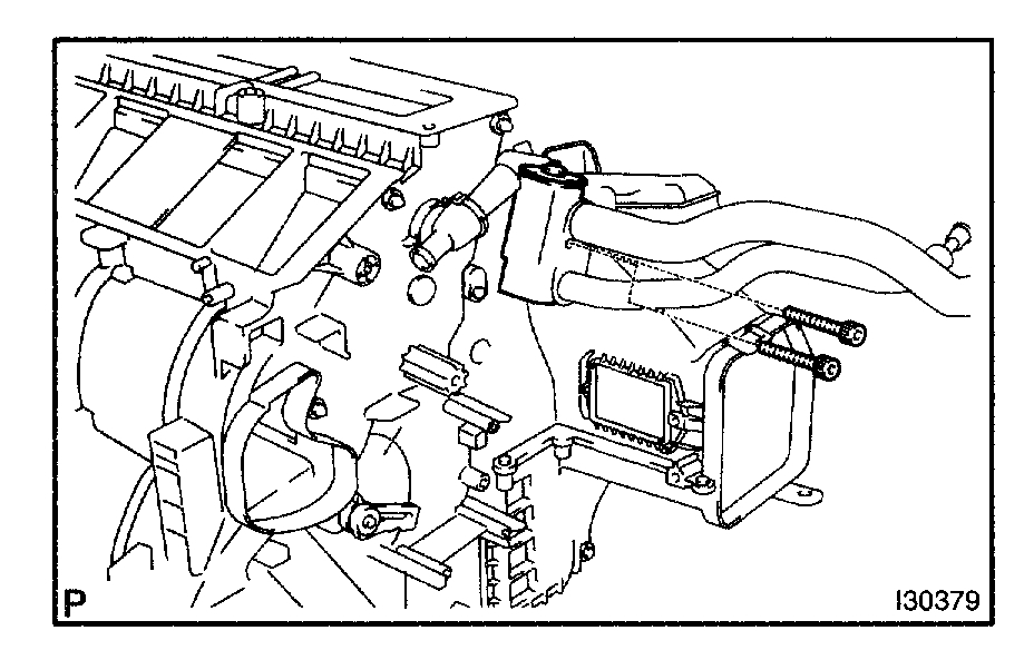
b. Remove the 4 screws and bracket.
C. Disconnect the connection between the blower assy and the air conditioner radiator assy and remove the latter assy.
Pic 24
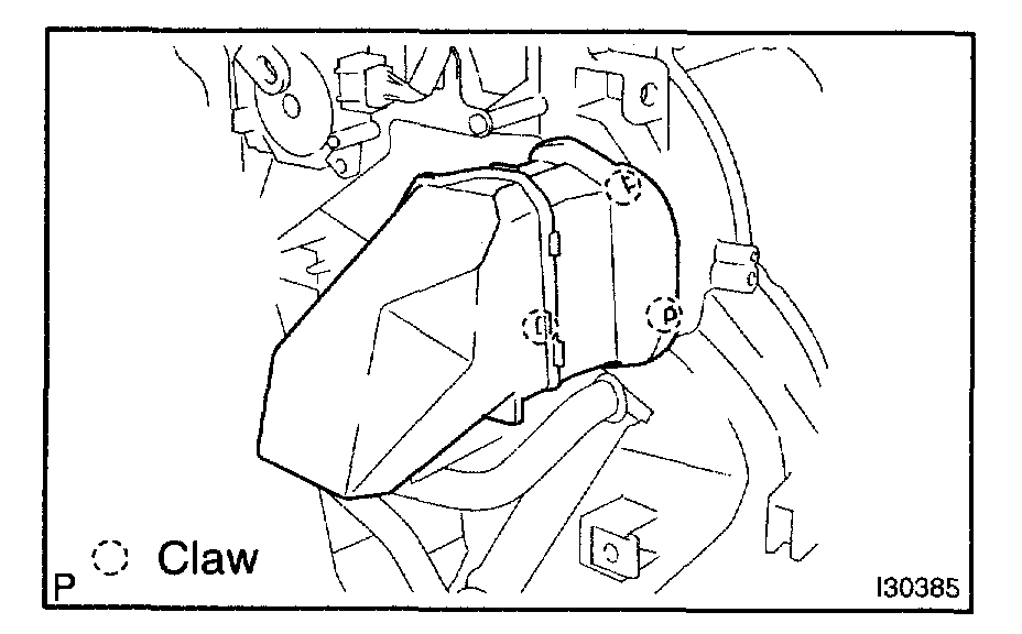
20. REMOVE AIR DUCT NO.1
a. Release the 3 claw fittings, remove the air duct No.1.
Pic 25
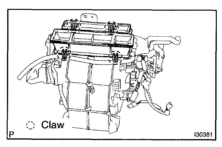
21. REMOVE HEATER TO REGISTER DUCT CENTER
a. Release the 4 claw fittings, remove the heater to register duct center.
Pic 26
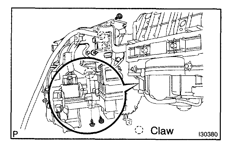
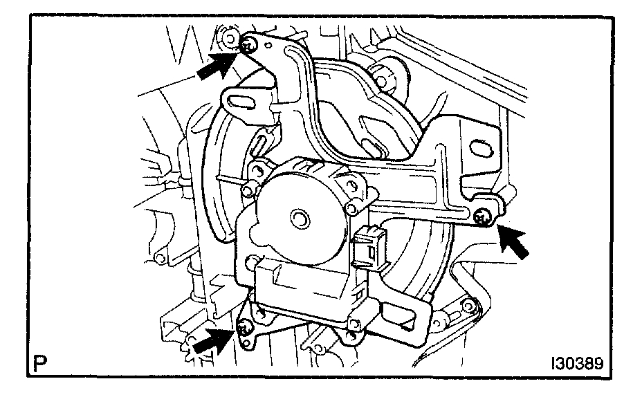
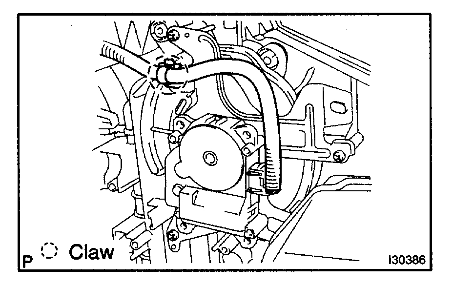
22. REMOVE MODE DAMPER SERVO SUB-ASSY
a. Remove the 3 screws and mode damper servo sub-assy.
Pic 27
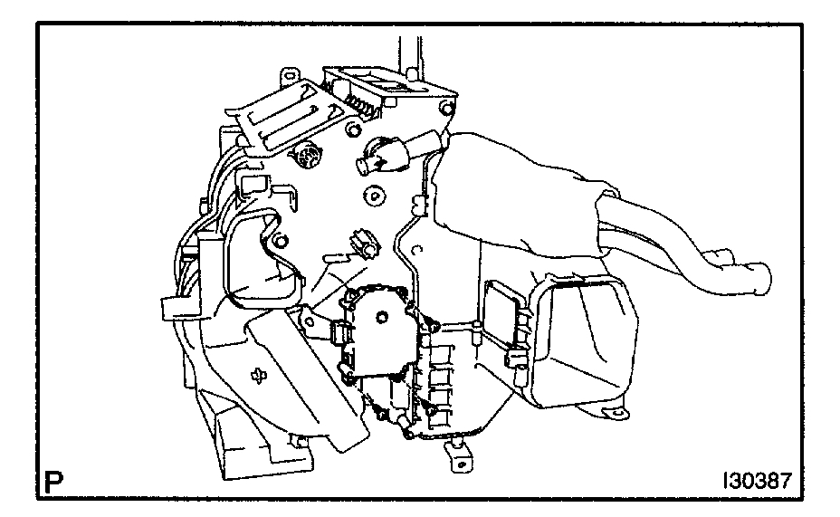
23. REMOVE WIRING AIR CONDITIONING HARNESS SUB-ASSY
a. Remove the air conditioning harness sub-assy from the air conditioner radiator assy.
Pic 28
24. REMOVE AIR MIX DAMPER SERVO SUB-ASSY
a. Remove the 3 screws and airmix damper servo sub-assy.
Pic 29
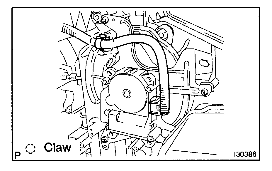
25. REMOVE HEATER RADIATOR UNIT SUB-ASSY
a. Remove the screw and clamp.
B. Remove the heater radiator unit sub-assy from the air conditioner radiator assy.
26. REMOVE COOLER THERMISTOR NO.1
pic 30
27. REMOVE BLOWER MOTOR CONTROL (AUTO AIR CONDITIONER)
a. Remove the 2 screws and blower motor control.
28. REMOVE BLOWER RESISTOR (MANUAL AIR CONDITIONER)
a. Remove the 2 screws and blower resistor.
29. REMOVE WIRING AIR INDICATOR HARNESS SUB-ASSY NO.2
a. Remove the wiring air indicator harness sub-assy No.2 from the blower motor control.
Pic 31
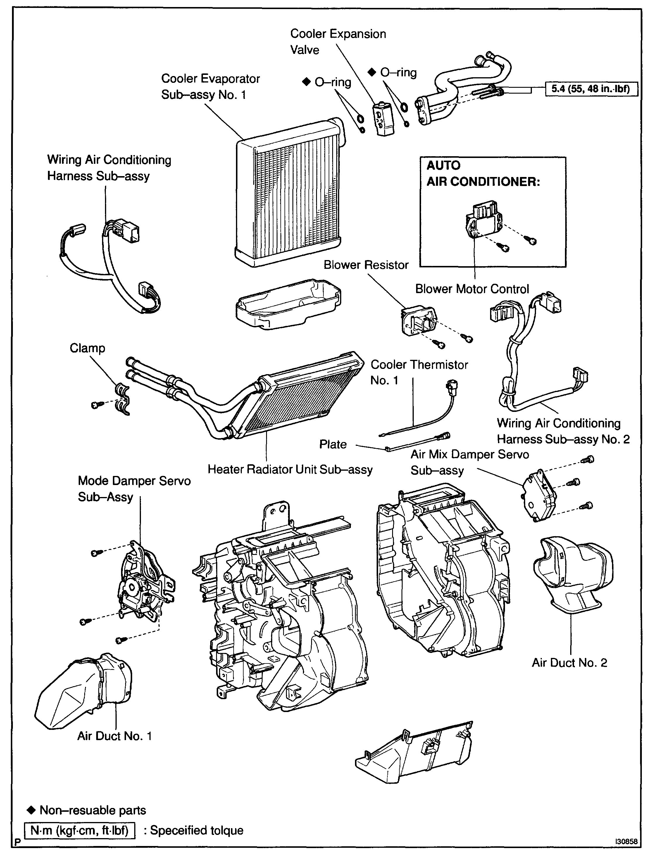
30. REMOVE COOLER EXPANSION VALVE
a. Using a hexagon wrench 4 mm, remove the 2 hexagon bolts and cooler expansion valve.
B. Remove the 2 O-rings from the air conditioner tube assy.
Pic 32
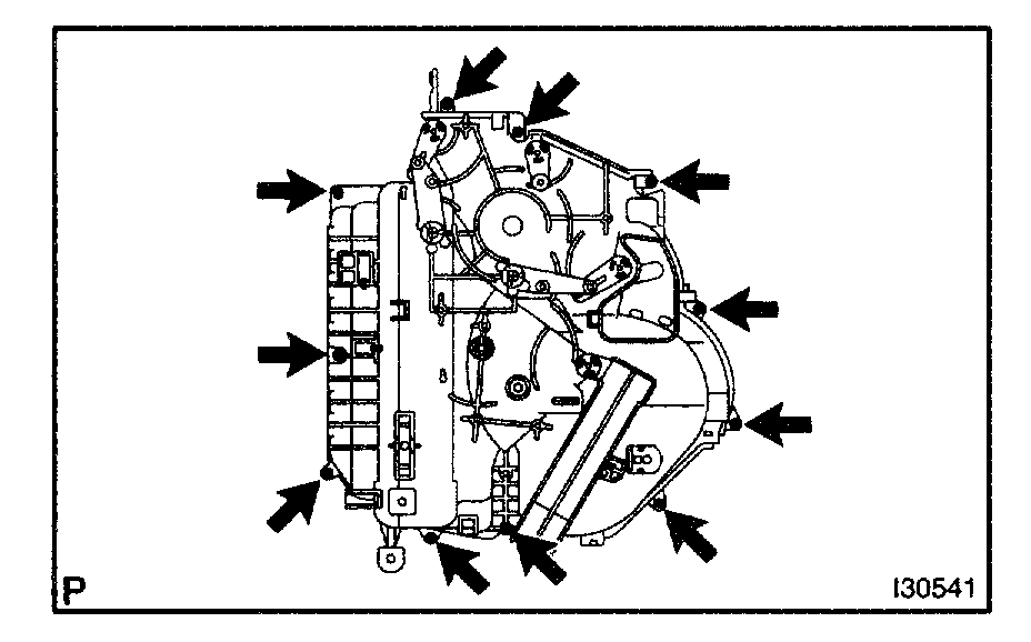
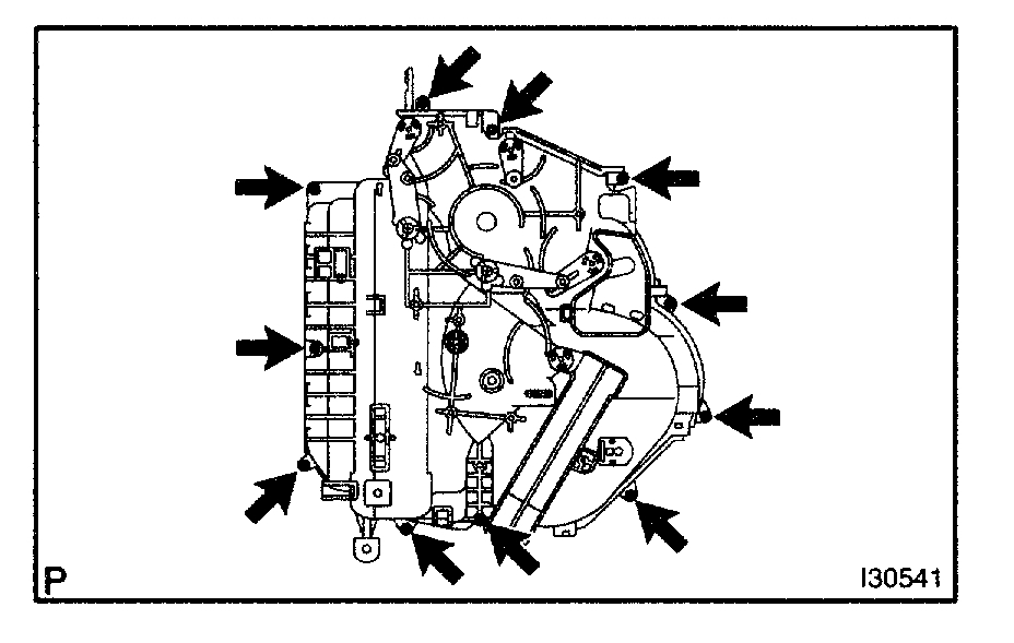
31. REMOVE COOLER EVAPORATOR SUB-ASSY NO.1
a. Remove the 11 screws and disassemble the air conditioner radiator assy.
B. Remove the cooler evaporator sub-assy No.1 from the air conditioner radiator assy.
C. Remove the 2 O-rings from the cooler evaporator sub-assy No.1.
Pic 33
32. INSTALL COOLER EVAPORATOR SUB-ASSY NO.1
a. Install the cooler evaporator No.1 to the air conditioner radiator assy.
B. Reassemble the air conditioner radiator assy with 11 screws.
Pic 34
33. INSTALL COOLER EXPANSION VALVE
a. Apply compressor oil to the contact surfaces of 2 new 0-rings and the air conditioner tube assy and install them.
Compressor oil: ND-OIL 8 or equivalent
b. Using a hexagon wrench 4, install the cooler expansion valve and 2 hexagon bolts to the cooler evaporator No.1.
Torque: 5.4 N.M (55 kgf. Cm, 48 in. Lbf)
pic 35
34. INSTALL AIR CONDITIONER UNIT ASSY
a. Install the air conditioner unit assy with the 3 bolts and 2 nuts.
Torque: 9.8 N.M (100 kgf. Cm, 87 in. Lbf)
b. Connect the connectors connecting the wiring air indicator No.2 harness and vehicle harness.
Pic 36
c. Install the connector and clamp.
Pic 37
35. INSTALL INSTRUMENT PANEL REINFORCEMENT ASSY
a. Install the instrument panel reinforcement assy, 5 bolts and 4 nuts.
Torque: 29 N.M (300 kgf. Cm, 21 ft. Lbf)
pic 38
36. INSTALL SKID CONTROL ECU ASSY
a. Install the 2 nuts and skid control ECU assy.
Torque: 5.0 N.M (50 kgf. Cm, 43 in. Lbf)
pic 39
37. INSTALL INSTRUMENT PANEL JUNCTION BLOCK ASSY
a. Install the instrument panel junction block assy, bolt and 2 nuts.
Torque: 8.4 N.M (86 kgf. Cm, 74 in. Lbf)
pic 40
38. INSTALL ECM
a. Install the ECM and 2 nuts.
Torque: 5.5 N.M (56 kgf. Cm, 49 in. Lbf)
pic 41
39. INSTALL INSTRUMENT PANEL BRACE SUB-ASSY NO.2
a. Install the instrument panel brace sub-assy No.2, 2 bolts and 2 nuts.
Torque: 29 N.M (300 kgf. Cm, 21 ft. Lbf)
pic 42
40. INSTALL INSTRUMENT PANEL BRACE SUB-ASSY NO.1
a. Install the instrument panel brace sub-assy No.1, 2 bolts and 2 nuts.
Torque: 29 N.M (300 kgf. Cm, 21 ft. Lbf)
pic 43
41. INSTALL FLOOR SHIFT ASSY
a. Install the 4 nuts and floor shift assy.
Torque: 20 N.M (200 kgf. Cm, 14 ft. Lbf)
pic 44
b. Install the 2 nuts and shift cable.
Torque: 20 N.M (200 kgf. Cm, 14 ft. Lbf)
pic 45
42. INSTALL STEERING COLUMN ASSY
a. Install the steering column assy, 2 bolts and 2 nuts.
Torque: 21 N.M (210 kgf. Cm, 15 ft. Lbf)
43. INSTALL INSTRUMENT PANEL SAFETY PAD SUB-ASSY
pic 46
44. INSTALL COOLER REFRIGERANT SUCTION PIPE NO.1
a. Lubricate new O-ring with compressor oil and install them to the hose.
Compressor oil: ND-OIL 8 or equivalent
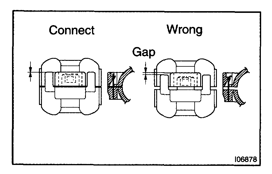
b. Install the cooler refrigerant suction hose No.1 and piping clamp.
HINT: After connection, check the fitting for claw of the piping clamp.
45. INSTALL COOLER REFRIGERANT LIQUID PIPE A
HINT: Install in the same way as the cooler refrigerant suction pipe No.1.
46. ADD COOLANT
1MZ-FE:
2AZ-FE:
47. CHECK ENGINE COOLANT LEAK
48. CHARGE REFRIGERANT
49. WARM UP ENGINE
50. INSPECT LEAKAGE OF REFRIGERANT
_________________________________________________________
Let me know if this helps.
Joe
Images (Click to make bigger)
Saturday, September 19th, 2020 AT 12:21 PM
(Merged)