How to bypass gm computer controlled alternator

Tiny
VERNON ANDERSON
  • MEMBER
  • 2002 CHEVROLET S-10
  • 2.2L
  • 4 CYL
  • 2WD
  • MANUAL
  • 200,000 MILES
Here is a problem that someone with a true understanding of the GM algorithm and their PCM may be able to help me with.
I am visiting family out of town and I need to resolve this to get back home by the end of next week. This will be a twelve hour drive and I fear breaking down on the highway.
Four days ago my truck listed above (L4) started in a store parking lot and got me to my mom’s home, but the dash and head lights were dimmed, the radio cycled down multiple times and the battery light came on and the dash volt meter showed about ten volts. I verified this with my Fluke 83 DVOM, but had to stop as it was getting dark and starting to rain.
The next morning with meter and amp probe in hand I started the truck up and showed 13.2 volts at the alternator with a 0.075vdp to the battery and a 58.5A draw to run all of the trucks accessories and charge the battery. Within five minutes the voltage rose to 14.1 volts and the amps dropped to 30 amp with most of the accessories turned off.
After shutting down the engine and restarting the truck the battery light, gauge and meter all confirm the truck voltage was 12.2 volts and dropping with no output current from the alternator. I shut down the engine at 11.5 volts. After a few hours the truck was restarted with the alternator’s output returning to normal.
I have been able to duplicate this cycle four times in three days.
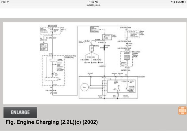
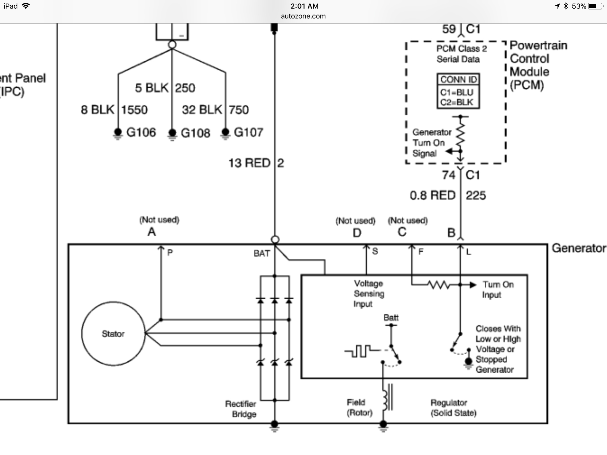
After finding and downloading a schematic as best I can determine the single sixteen gauge wire coming off the alternator only tells the alternator “when” to charge and not “how much” as the voltage is a constant 4.70 volts input when the alternator is charging, and drops to less than 1.5 volts when the truck is hot and restarted with no output from the alternator.
My questions are: Am I correct about how this charging system works? Are there any inputs to the PCM that should trigger the PCM to turn off the alternator under these conditions, and what should I look for? Has the PCM fail and can I verify it?
Sorry for the lengthy story, but I have worked in the diesel industry in Customer, Tech, and Dealer support. And I have always hated when people call me to tell them what part to replace with minimal details and no troubleshooting trail as if I had a crystal ball.
Thursday, January 11th, 2018 AT 10:46 AM

4 Replies

Tiny
CARADIODOC
  • MECHANIC
  • 33,741 POSTS
Where are you finding 1.50 and 4.70 volts?

I suspect you are over-thinking the issue. GM redesigned their generators for the 1987 model year, and in my opinion, went from the world's second-best design to by far the worst pile ever pushed on their customers. These have an extremely high failure rate because they develop huge voltage spikes that can damage the internal diodes and voltage regulator, and interfere with computer sensor signals. The battery is the key component in damping and absorbing those spikes, but as they age and the lead flakes off the plates, they lose their ability to do that. It is not uncommon to go through four to six generators in the life of the truck, but to reduce that number of repeat failures, always replace the battery at the same time, unless it is less than about two years old.

You did a perfect job of describing a voltage regulator failure. GM likes to build their parts into assemblies that go together quickly on the assembly line, and their generators are another example. It is not practical to replace just the regulator because getting the generator apart is very frustrating. Most commonly, the tabs break off the diode block when you are trying to unsolder the wires through the housing, so you will need to replace that block. With the high difficulty and time involved in getting it apart, you are not going to risk reusing the old regulator that might be defective. There is no way to measure continuity of the brushes, so change those too. By the time you are done, you will have more in it than if you bought a professionally-rebuilt unit with a warranty.

To answer your question about system operation, when you turn on the ignition switch, current flows through the "gauges" fuse, through the "battery" light, then through the brown wire to the plug on the side/back of the generator. That plug is part of the regulator. Ten volts is dropped across the light. The two volts on the brown wire is the "turn-on" circuit that tells the regulator to pass current through the field winding to make the magnetic field. That current comes from the battery and the fat output wire on the back of the generator.

Once the engine is running and the generator is developing output, the regulator looks internally to watch system voltage. When it is satisfied, it puts full system voltage back out on the brown wire. With the same voltage on both sides of the bulb, it turns off.

GM digital dashboards flicker from tiny voltage variations from everything from injector pulses to arcing brushes in heater fan motors and power window motors. To address that, vehicles with digital dashes will have a system voltage sensing wire going to a second terminal next to the brown wire in the generator's plug. There is no harm in the voltage in the rest of the electrical system varying by a few hundredths of a volt, but by watching the voltage at the instrument cluster and holding that steady, the flickering brightness can be reduced.

A failed diode is also real common, but those are rarely intermittent. Once one fails, all you will be able to get during a full-load output current test is exactly one third of the unit's rated current. "Ripple voltage" will be very high. The engineers use zener diodes to try to reduce the number of voltage spikes, but they had limited success.
Was this
answer
helpful?
Yes
No
+1
Thursday, January 11th, 2018 AT 6:32 PM
Tiny
VERNON ANDERSON
  • MEMBER
  • 2 POSTS
CARADIODOC,
Thanks for the prompt reply. Attached is the wire diagram I receive and used to do my troubleshooting. There is no brown wire on this model. Only the output red wire and a second red wire that runs to pin # 74 C1 of the PCM from the alternator regulator.I am guessing that as with many control module inputs and outputs that this is a five volt circuit and that nominal voltage would be 4.5-5.0v.
When the engine is started cold the PCM is supplying 4.7 volts to the regulator on the alternator, the voltage and amps at the output terminal of the alternator and battery are nominal. The alternator will continue to charge even when hot until the engine is shut down. When the truck is hot the PCM supplied voltage to the alternator drops to 1.5 volts or less and the output of the alternator goes to 0 amp and 0 volts when the truck is restarted. This also happens when this wire is unplugged from the alternator.
Please correct me if I am wrong, but this appears to be a control circuit to activate the alternator. If it is not I would appreciate it if you could explain it for me as I am not familiar with GM’s protocol and programming as all of my training has been with diesels and I have worked as a trainer in this field.
If this does turn out to be a control circuit, is there a reason for a properly functioning PCM to do this or has it failed.
Was this
answer
helpful?
Yes
No
+1
Friday, January 12th, 2018 AT 11:57 PM
Tiny
ASEMASTER6371
  • MECHANIC
  • 52,797 POSTS
Good morning.

I would remove the alternator and take it to a parts store and have them check it. They have the machines that can run it and test it under load to confirm it is a failed alternator. PCM failure for this is rare.

Roy
Was this
answer
helpful?
Yes
No
Saturday, January 13th, 2018 AT 5:26 AM
Tiny
CARADIODOC
  • MECHANIC
  • 33,741 POSTS
You are still describing a failed voltage regulator. That smaller red wire is still the turn-on circuit. It just comes through more complicated computer circuitry as before. Since the mid to late 1980's, Chrysler has built their regulators into the engine computer so it can adjust for all the variables the computer knows about. Since they invented the electronic regulator for 1970 models, they have always had temperature compensation built in to bump up charging voltage a little when battery temperature was cold. With the regulator built into the computer, it can increase, reduce, or stop output for things like wide-open-throttle, load from the AC compressor, coolant temperature, and things like that.

This is GM's attempt at adjusting output for that variety of conditions. The circuit coming from the PCM is still the turn-on circuit, and the voltage regulator still sends a voltage back to tell the PCM it is working. You are losing that verification voltage. That would be the equivalent on older vehicles of losing the twelve volts it puts on the "battery" light to turn it off.

I am not a fan of testing generators and starters off the engine, especially in this case. The problem does not occur right away, so the unit will test fine. The testing needs to be done while the problem is occurring. That could mean running the test bench for hours.

What you might consider is disconnecting the plug on the generator, then connect a small jumper wire to that terminal that had the red wire. Hook that jumper to a 3057 brake light bulb, and hook the other bulb terminal to the battery's positive post. That will be the dash light bulb. You should see the bulb turn off as soon as the engine starts running. If it turns off when the charging problem occurs, replace the generator.

I have to question though whether there is a significant difference between this generator, which goes back to 1998 models, and the older version that used the dash light. My bulb test will work on the older versions. If it does not work on your model, you will have to go by the loss of feedback voltage.
Was this
answer
helpful?
Yes
No
Saturday, January 13th, 2018 AT 1:21 PM

Please login or register to post a reply.

Sponsored links