Excuse me, guys, but I have to stick my nose in here. I'm pretty sure Steve is busy forming an appropriate reply. I'm just following along to learn the solution.
You must NEVER, EVER remove a battery cable while the engine is running. A mechanic caught pulling this stunt might get one verbal warning, but more likely he will be fired. This is the single best way to destroy multiple computers and burn out any lights that are turned on. This was a trick done in the 1960s when mechanics didn't understand how these simple systems work or how to diagnose them. The results are completely invalid. An engine with a good generator might stall, and one with a defective generator can stay running, so what good is that "test"?
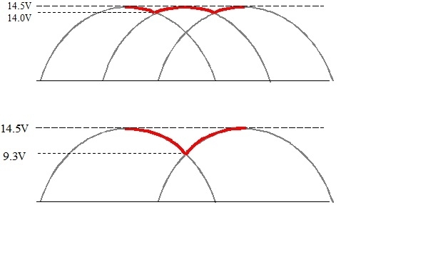
All "AC generators" develop three-phase output, like what's shown in the top waveform in my drawing. The red line on top shows the normal "ripple" voltage that you'd see with an oscilloscope. That alone would cause a very annoying whine on AM radio, but it's the battery's job to smooth that out. Ripple voltage doesn't cause other problems except when there is no battery, or in the case of '87 and newer GM generators, can result in huge, damaging voltage spikes that lead to repeat generator failures. What is of concern is how the voltage regulator reacts to ripple voltage.
The voltage regulator's goal is to maintain system voltage between 13.75 to 14.75 volts, (give or take a little depending on which textbook you read). Normally it looks at battery voltage. There are exceptions, mainly on GM vehicles with digital instrument clusters, but that's not important to this sad story. Lets use 14.0 volts for this explanation. As I drew in this diagram, without the battery connected, the voltage regulator would "see" 14.0 volts very briefly. Most of the time system voltage is higher. Some regulators would respond by trying to lower those higher voltages. It does that by cutting back on generator output, but with no battery, it does that without success. Even though average voltage drops, the regulator still reacts to the instances when voltage goes over 14.0 volts. It eventually cuts back so far, the engine stalls due to voltage to the ignition coils, injectors, and electric fuel pump being too low to operate properly. Since the engine stalled, you incorrectly think the generator is defective.
More commonly, most voltage regulators respond to the lower system voltages, in my drawing that would be the 14.0 volts. If it's trying to maintain system voltage of, . . . say, . . . 14.2 volts, it will see the 14.0 volts and try to bump up generator output. The peaks may go to 15, 16, even 18 volts, but it's still reacting to the 14.0 volts. No matter how high output voltage goes, it keeps on seeing voltage that's too low. It's the battery that keeps the regulator seeing a nice, steady 14.2 volts. I did this every year for a class demonstration. With the generator on a test bench, and the battery disconnected, it was very easy to get the output voltage to exceed 30 volts. That would be catastrophic to any vehicle with computers or older ignition modules.
What CAN save you with this procedure is to generate a voltage mechanically, you need three things. Those are a wire, (coil of wire is more efficient), a magnetic field, (we use an electromagnet because it's easily adjustable), and most importantly, movement between them. That's why we spin the electromagnet with a belt and pulley. Because of that movement, all generators are rather inefficient at low speeds, like engine idle speed. That's also why all professional testers include "raising engine speed to 2,000 rpm" as part of the procedure.
Where this becomes more confusing is when a diode fails. "Diodes" are one-way valves for electrical current flow. All AC generators use at least six of them. Two are used in each phase, or group of coils, but they share and trade off which coils they're working for as the magnetic field rotates. The bottom line is when one diode fails, you lose one phase, as shown in my lower drawing. Ripple voltage goes extremely high, 5.2 volts in this case, and you lose exactly two-thirds of the generator's output current capacity. Today it's very common to find generators with a rating of 100 amps. With one failed diode, the most you'll be able to get under the "full-load output current" part of the professional test is around 33 amps. That isn't enough to run the entire electrical system under all conditions. The battery has to make up the difference as it slowly runs down over days or weeks. Even worse, the voltages in my drawings are just representative as part of the explanation. On the car, these voltages can be much higher and can be basically uncontrollable with the battery disconnected. This is a case where the generator is defective but the engine will likely stay running, (poorly), with the battery disconnected.
You can also have a dead charging system caused by something other than the generator. Not all voltage regulators are built into the generators. Some are in different places, with wiring and connector terminals in the circuit. Those are good places to find very simple defects causing these failures of the battery to charge.
The proper way to test the charging system is to simply measure the battery's voltage. Do that first with the engine off. If the voltage is close to 12.6 volts, it's good and fully charged. (The battery can still be aged and have lost most of its cranking power, but that's a different part of this story). If you find it's closer to 12.2 volts, it's good but fully discharged. Charge it at a slow rate with a portable charger for a few hours. If you find it's around 11 volts or less, it has a shorted cell and must be replaced.
Next, measure the battery's voltage again with the engine running. Now it must be between 13.75 and 14.75 volts. It may be a little too low at first if the battery was run down. You'll see its voltage come up slowly over the next few minutes as it charges up. Don't get excited if the voltage is a little high. Some voltage regulators such as Chrysler's original design from 1970 have temperature compensation built in. Charging a battery is a chemical process, and those slow down in colder temperatures. They bump charging voltage up a little in cold weather to help that process.
If your battery voltage tests pass, that only means it is okay to perform the rest of the tests, but those require the professional load tester. That will measure full-load output current and ripple voltage. This is the only time in the generator's life it will be asked to develop the maximum current it's capable of.
If you find under the full-load output current test, the most you can get is around one third of what you expect, you're going to find ripple voltage is high too. Both conditions signal a failed diode. There are a few professional load testers that can make paper printouts. Those can list ripple voltage as an actual voltage. Most testers, however, just show ripple voltage as "low" or "high" with a series of flashing lights.
The last condition I'll describe has to do with worn brushes inside the generator. Those always start out as an intermittent problem that acts up for a few minutes, then maybe not again for days or weeks. Over more miles, that becomes more often and for longer and longer periods of time, so you do get plenty of warning. On most models other than the '87 and newer GM generators, those brushes can usually be replaced by a competent do-it-yourselfer, especially with me or Steve looking over your shoulder. The point in mentioning this is to identify this defect, any testing has to be done while the problem is occurring. If you have the system tested by your mechanic while the problem isn't occurring, it's going to falsely appear to be okay.
To get into more specific testing, we can help with that too on some brands. Fords, in particular were pretty nice throughout the 1990s, but then the engineers figured out it needed to be more difficult, so they addressed that by adding a cover over the back of their generators. Starting the testing on Chrysler's systems is very easy, but there is one time when you need my simple trick to know which terminal to test on. Don't waste your time on GM systems. They had, in my opinion, the world's second best system up through 1986, then they redesigned them and came up with the worst system to work on.
As long as I'm already intruding, I have two more comments of value. First, if you remove a battery cable with the engine off, to measure for a current drain. it doesn't matter if that's done at the positive or negative cable. You will find the same current at either place, at the same time. If you found different readings, that could be due to the next comment.
On vehicles as new as yours, there are likely to be some computers that need to time out after the ignition switch is turned off. That can take up to 20 minutes, and can be as high as three amps. You have to wait for that to occur before doing any testing. To add to the frustration, anything you do to break the circuit, even for an instant, can start the wake-up cycle all over, then you have to wait again. That can include a meter probe slipping off it's measurement point, moving the positive probe to a different jack on the meter, and even simply switching the range switch to a different scale. I put together a description of how I handle that. I'll let Steve continue with your conversation, then I'll pop back if asked.
Again, I'm sorry for butting in here, but this is too important to overlook. Steve does an uncommonly good job of guiding you through the proper repairs. I'm pretty sure he will be back with more help for you.
Jan 3, 2026 at 8:28 PM