Hi and thanks for using 2CarPros.com.
The code indicates the engine coolant temperature sensor (ECT) is indicating the engine isn't warm enough. The sensor which correlates with this tells the computer the coolant temperature. From that, the computer determines what the fuel/air ratio should be for the engine.
Since the gauge is giving you trouble at times inside, (which is a different sensor), I have a feeling the thermostat is stuck open and not allowing the vehicle to meet the minimum recommended operating temp. However, the sensor could be the issue.
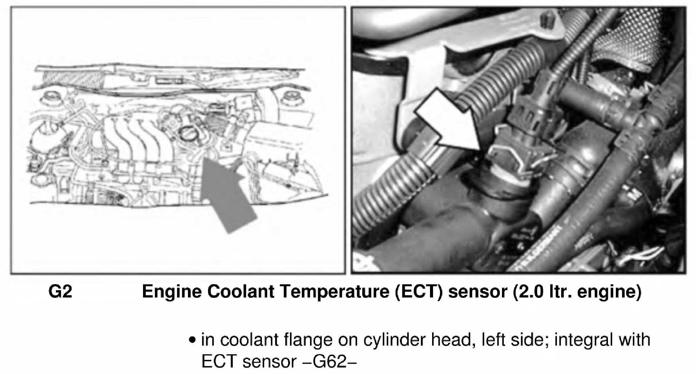
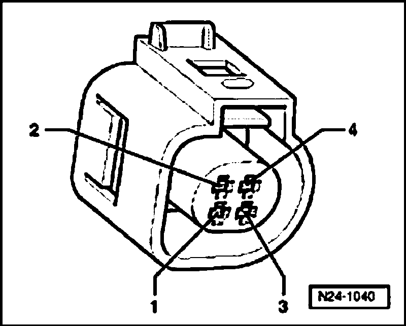
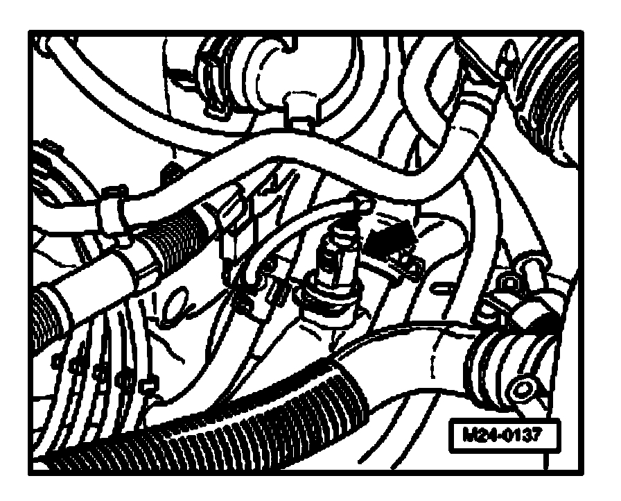
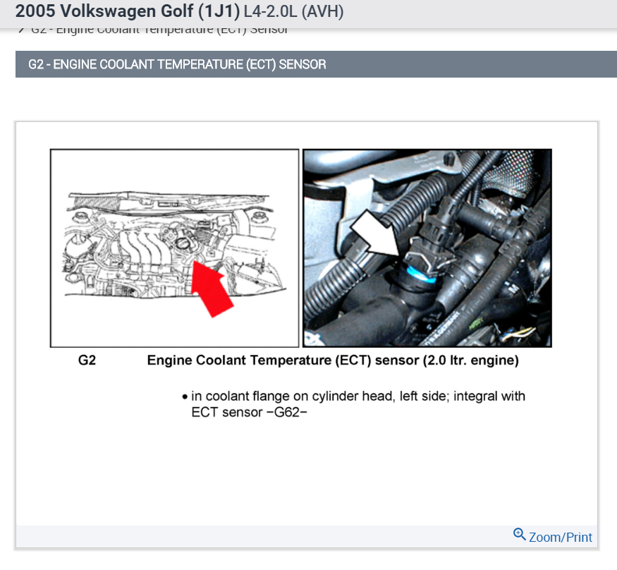
Pic 1 is the ECT. It shows where it is located and what to look for.
I have attached the directions for checking the sensor, but to be honest, it is very extensive. You indicated that you are a mechanic, so I am sure you are familiar with this type of trouble shooting information. All remaining pictures correlate with these directions.
______________________________________
COMPONENT TESTS AND GENERAL DIAGNOSTICS
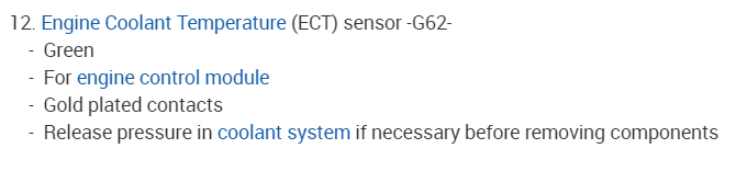
Engine Coolant Temperature (ECT) Sensor, Checking
NOTE: Use only gold-plated terminals when servicing terminals in harness connector of sensor.
Recommended special tools and equipment
- V.A.G 1526 multimeter or V.A.G 1715 multimeter
- V.A.G 1594 connector test kit
- Wiring diagram
Requirements
- The respective fuses of Motronic Engine Control Module (ECM) -J220- must be OK.
- Parking brake must be engaged or else daylight driving lights will be switched on.
- For vehicles with automatic transmission, selector lever must be in position -P- or -N-.
- Engine must be cold.
Function test, vehicles with engine code AEG
- Connect diagnostic tester. See: Computers and Control Systems > Reading and Clearing Diagnostic Trouble Codes > Diagnostic Tester, Connecting
- Switch ignition on.
- Under address word 33, select "Diagnostic mode 1: Check measured values."
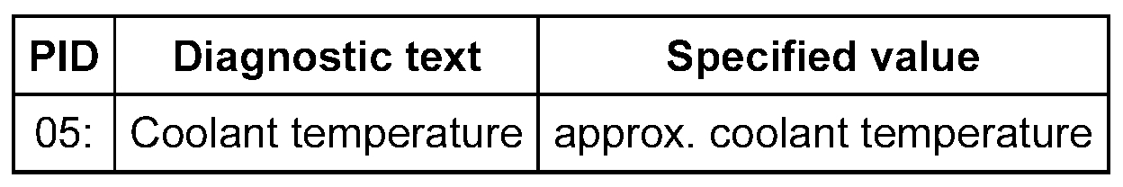
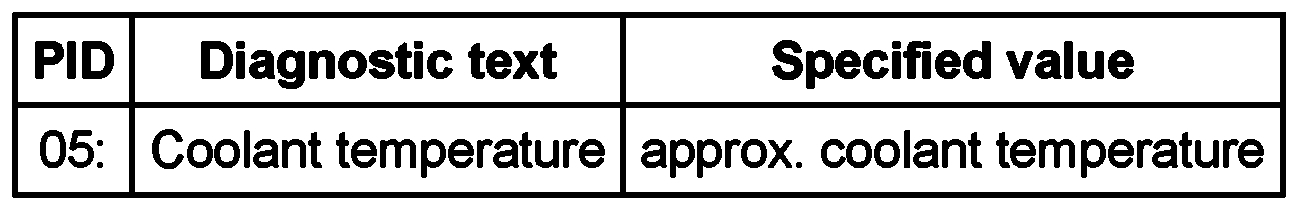
- Select the measuring value "PID 05: Coolant temperature".
- Check specified value of coolant temperature:
If specified value is not obtained:
- Continue test according to the following table:
If specified value is obtained.
- Start engine and let run at idle. The temperature must climb uniformly.
NOTE:
- The temperature increases in increments of 1.0 degree C.
- If the engine shows problems in certain temperature ranges and if the temperature does not climb uniformly, the temperature signal is intermittent and the sensor should be replaced.
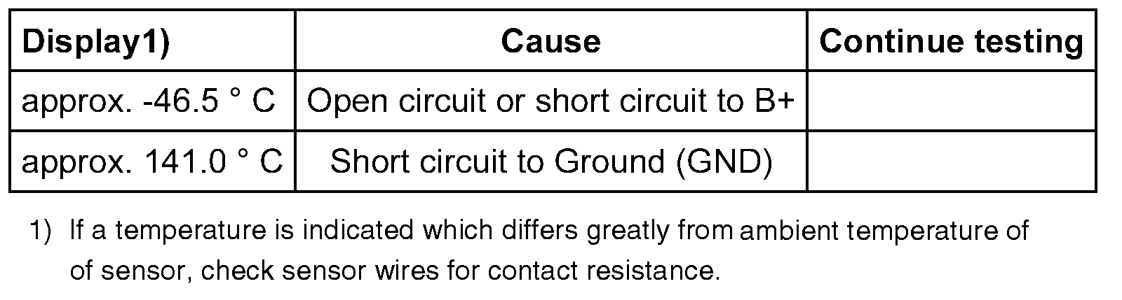
Continuation of test if indication is approx. -46.5 degrees C
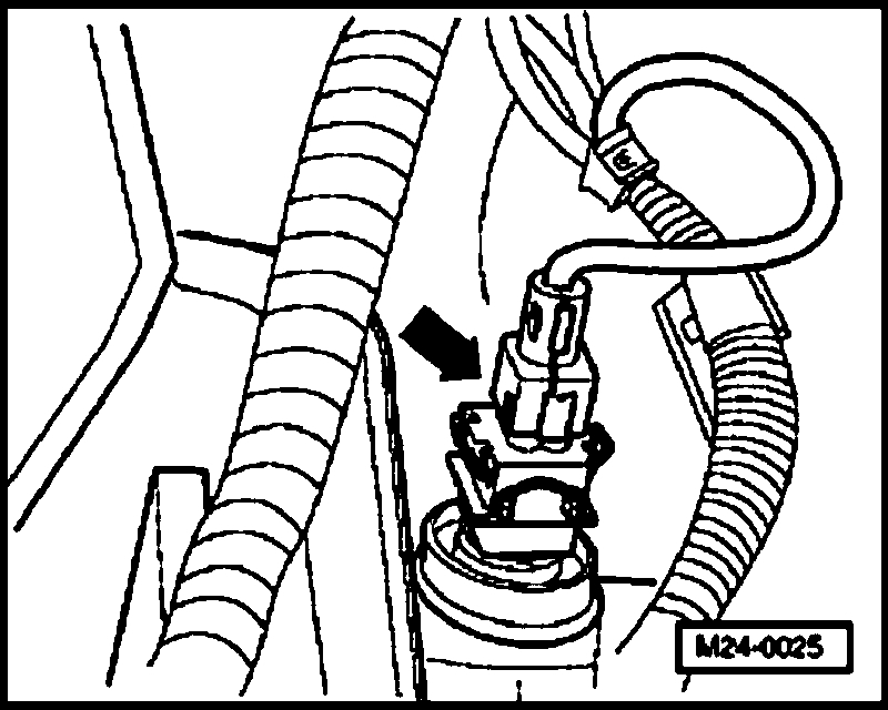
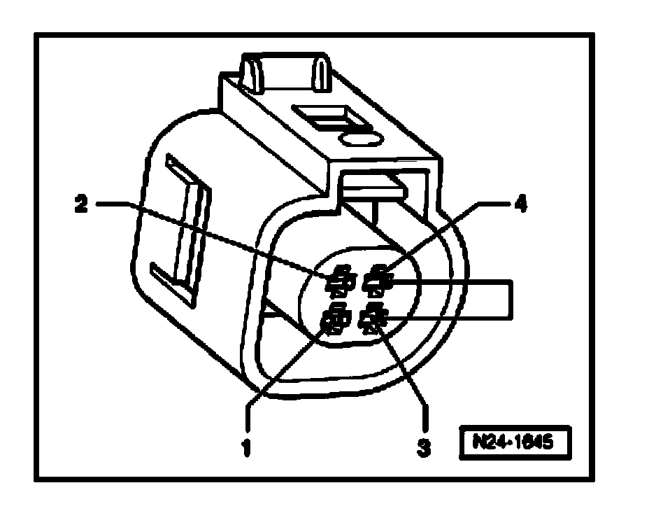
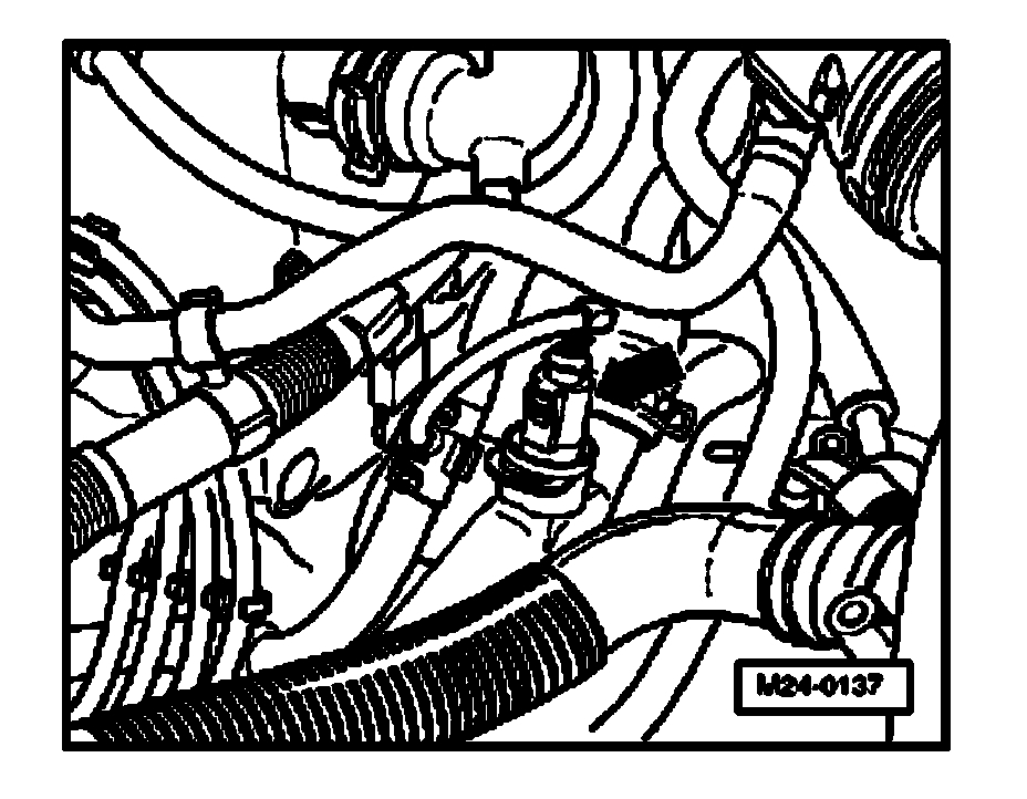
- Disconnect 4-pin connector from Engine Coolant Temperature (ECT) sensor -G62- with Engine Coolant Temperature (ECT) sensor -G2- (arrow).
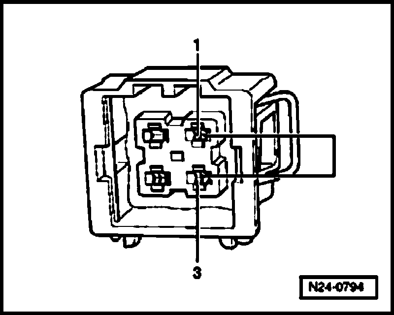
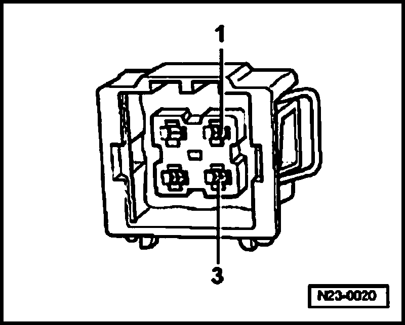
Vehicles with old connector shape
- Bridge terminals 1 + 3 of connector using the respective adapter cables and observe the indication on display.
Vehicles with new connector shape
- Bridge terminals 3 + 4 of connector using the respective adapter cables and observe the indication on display.
Continued for all connector shapes
If indication jumps to approx. 141.0 degrees C
- End diagnosis and switch ignition off.
- -Replace Engine Coolant Temperature (ECT) sensor -G62- with Engine Coolant Temperature (ECT) sensor -G2-.
WARNING:
- The cooling system is under pressure.
- Danger of scalding when opening.
- Erase DTC memory of Engine Control Module (ECM), Diagnostic mode 4: Reset/erase diagnostic data. See: Computers and Control Systems > Scan Tool Testing and Procedures > Diagnostic Mode 4: Reset/Erase Diagnostic Data
- Generate readiness code. See: Computers and Control Systems > Monitors, Trips, Drive Cycles and Readiness Codes.
If indication remains at approx.-46.5 degrees C
- End diagnosis and switch ignition off.
- Check wires according to wiring diagram.
Continuation of test if indication is approx. 141.0 degrees C
- Disconnect 4-pin connector from Engine Coolant Temperature (ECT) sensor -G62- with Engine Coolant Temperature (ECT) sensor -G2- (arrow).
If indication jumps to approx. -46.5 degrees C
- End diagnosis and switch ignition off.
- Replace Engine Coolant Temperature (ECT) sensor -G62- with Engine Coolant Temperature (ECT) sensor -G2-.
WARNING:
- The cooling system is under pressure.
- Danger of scalding when opening.
- Erase DTC memory of Engine Control Module (ECM), Diagnostic mode 4: Reset/erase diagnostic data. See: Computers and Control Systems > Scan Tool Testing and Procedures > Diagnostic Mode 4: Reset/Erase Diagnostic Data
- Generate readiness code. See: Computers and Control Systems > Monitors, Trips, Drive Cycles and Readiness Codes.
If indication remains at approx. 141.0 degrees C
- End diagnosis and switch ignition off.
- Check wires according to wiring diagram.
Checking wiring
- Connect test box to control module wiring harness, connect test box for wiring test. See: Computers and Control Systems > Reading and Clearing Diagnostic Trouble Codes > Test Box, Connecting For Wiring Test
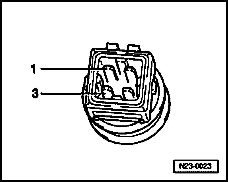
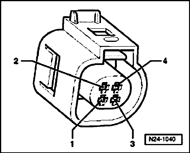
Vehicles with old connector shape (see pic)
- Check wires between test box and 4-pin connector for open circuit according to wiring diagram.
Terminal 1 + socket 67
Terminal 3 + socket 53
Wire resistance: max. 1.5 Ohms
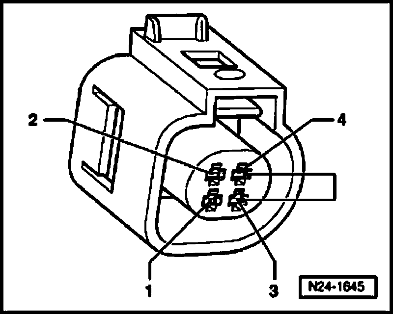
Vehicles with new connector shape (see pic)
- Check wires between test box and 4-pin connector for open circuit according to wiring diagram.
Terminal 3 + socket 93
Terminal 4 + socket 108
Wire resistance: max. 1.5 Ohms
Continuation for all connector shapes
- Check wires for short circuit to each other, to vehicle Ground (GND) and to B+.
Specified value: Infinite Ohms
If no malfunctions are found in wires:
Vehicles with old connector shape
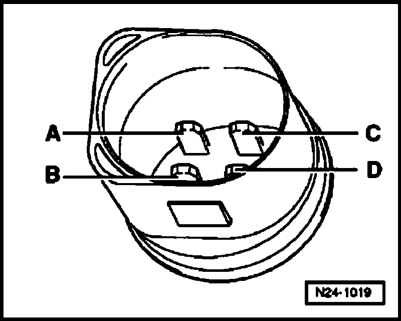
- Perform a resistance measurement at Engine Coolant Temperature (ECT) sensor -G62- terminal 1 (Ground) and 3 (signal).
Vehicles with new connector shape
- Measure resistance at Engine Coolant Temperature (ECT) sensor -G62-, terminals C (signal) and D (Ground).
Continuation for all connector shapes
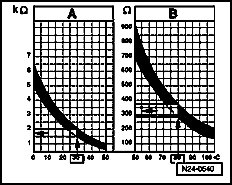
Range A displays resistance values for temperature range of 0 to 50 degrees C, range B displays resistance values for temperature range of 50 to 100 degrees C.
Read-out examples:
- 30 degrees C is in range A and corresponds to a resistance of 1.5 to 2.0 kilo Ohms
- 80 degrees C is in range B and corresponds to a resistance of 275 to 375 Ohms
If specified value is not obtained:
- Replace Engine Coolant Temperature (ECT) sensor -G62- with Engine Coolant Temperature (ECT) sensor -G2-.
WARNING:
- The cooling system is under pressure.
- Danger of scalding when opening.
- Erase DTC memory of Engine Control Module (ECM), Diagnostic mode 4: Reset/erase diagnostic data. See: Computers and Control Systems > Scan Tool Testing and Procedures > Diagnostic Mode 4: Reset/Erase Diagnostic Data
- Generate readiness code. See: Computers and Control Systems > Monitors, Trips, Drive Cycles and Readiness Codes.
If no malfunctions are detected in the wires and the resistance values are OK:
- Replace Motronic Engine Control Module (ECM) -J220-.
Function test, vehicles with engine code AVH, AZG, BBW, BEV
- Connect diagnostic tester. See: Computers and Control Systems > Reading and Clearing Diagnostic Trouble Codes > Diagnostic Tester, Connecting
- Switch ignition on.
- Under address word 33, select "Diagnostic mode 1: Check measured values."
- Select measuring value "PID 05: Coolant temperature".
- Check specified value of coolant temperature:
If specified value is not obtained:
- Continue test according to the following table:
If specified value is obtained:
- Start engine and let run at idle. The temperature must climb uniformly
NOTE:
- The temperature increases in increments of 1.0 degree C.
- If the engine shows problems in certain temperature ranges and if the temperature does not climb uniformly, the temperature signal is intermittent and the sensor should be replaced.
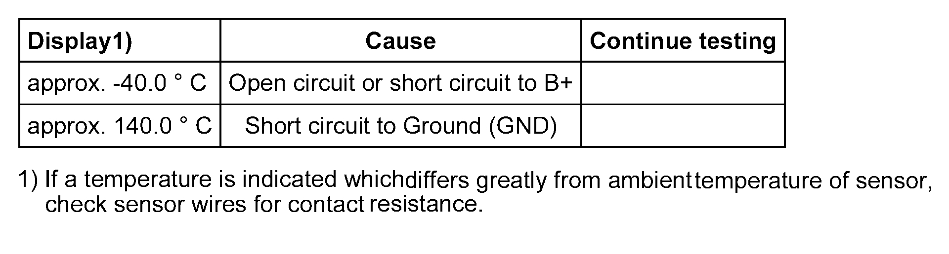
Continuation of test if indication is approx. -40.0 degrees C
- Disconnect 4-pin connector from Engine Coolant Temperature (ECT) sensor -G62- with Engine Coolant Temperature (ECT) sensor -G2- (arrow).
- Bridge terminals 3 + 4 of connector using respective adapter cables and observe indication on display.
If indication jumps to approx. 140.0 degrees C
- End diagnosis and switch ignition off.
- Replace Engine Coolant Temperature (ECT) sensor -G62- with Engine Coolant Temperature (ECT) sensor -G2-.
WARNING:
- The cooling system is under pressure.
- Danger of scalding when opening.
- Erase DTC memory of Engine Control Module (ECM), Diagnostic mode 4: Reset/erase diagnostic data. See: Computers and Control Systems > Scan Tool Testing and Procedures > Diagnostic Mode 4: Reset/Erase Diagnostic Data
- -Generate readiness code. See: Computers and Control Systems > Monitors, Trips, Drive Cycles and Readiness Codes.
If indication remains at approx. -40.0 degrees C
- End diagnosis and switch ignition off.
- Check wires according to wiring diagram.
Continuation of test if indication is approx. 140.0 degrees C
- Disconnect 4-pin connector from Engine Coolant Temperature (ECT) sensor -G62- with Engine Coolant Temperature (ECT) sensor -G2- (arrow).
If indication jumps to approx. -40.0 degrees C
- End diagnosis and switch ignition off.
- Replace Engine Coolant Temperature (ECT) sensor -G62- with Engine Coolant Temperature (ECT) sensor -G2-.
WARNING:
- The cooling system is under pressure.
- Danger of scalding when opening.
- Erase DTC memory of Engine Control Module (ECM), Diagnostic mode 4: Reset/erase diagnostic data. See: Computers and Control Systems > Scan Tool Testing and Procedures > Diagnostic Mode 4: Reset/Erase Diagnostic Data
- Generate readiness code. See: Computers and Control Systems > Monitors, Trips, Drive Cycles and Readiness Codes.
If indication remains at approx. 140.0 degrees C
- End diagnosis and switch ignition off.
- Check wires according to wiring diagram.
Checking wiring
- Connect test box to control module wiring harness, connect test box for wiring test. See: Computers and Control Systems > Reading and Clearing Diagnostic Trouble Codes > Test Box, Connecting For Wiring Test
- Check wires between test box and 4-pin connector for open circuit according to wiring diagram.
Terminal 3 + socket 93
Terminal 4 + socket 108
Wire resistance: max.1.5 Ohms
- Check wires for short circuit to each other, to vehicle Ground (GND) and to B+.
Specified value: Ohms
If no malfunctions are found in wires:
- Measure resistance at Engine Coolant Temperature (ECT) sensor -G62-, terminals C (signal) and D (Ground (GND)).
Range A displays resistance values for the temperature range of 0 to 50 degrees C, range B displays resistance values for the temperature range of 50 to 100 degrees C.
Read-out examples:
- 30 degrees C is in range A and corresponds to a resistance of 1.5 to 2.0 kilo Ohms
If specified value is not obtained:
- Replace Engine Coolant Temperature (ECT) sensor -G62- with Engine Coolant Temperature (ECT) sensor -G2-.
WARNING:
- The cooling system is under pressure.
- Danger of scalding when opening.
- Erase DTC memory of Engine Control Module (ECM), Diagnostic mode 4: Reset/erase diagnostic data. See: Computers and Control Systems > Scan Tool Testing and Procedures > Diagnostic Mode 4: Reset/Erase Diagnostic Data
- Generate readiness code. See: Computers and Control Systems > Monitors, Trips, Drive Cycles and Readiness Codes.
If no malfunctions are detected in the wires and the resistance values are OK:
- Replace Motronic Engine Control Module (ECM) -J220-.
__________________________________________
Let me know if this helps.
Take care,
Joe
Images (Click to enlarge)
Aug 13, 2018 at 5:58 PM