Hi and thanks for using 2CarPros.
Testing will require a scanner. Here are the diagnostics for checking. The attached pictures correlate with the directions and indicate the next procedure.
_________________________________________
COMPONENT INSPECTION
Engine Control
P2006 Intake Manifold Runner Control Stuck Closed (Bank 1) - Inspection/Repair:_:Component Inspection
Component Inspection
1. IG KEY "ON" and select 'Actuation Test' menu in GDS.
2. Execute 'Variable Charge Motion Actuator'.
3. Confirm the change of VCMA feedback sensor signal and the sound of operation.
Specification
Picture 1
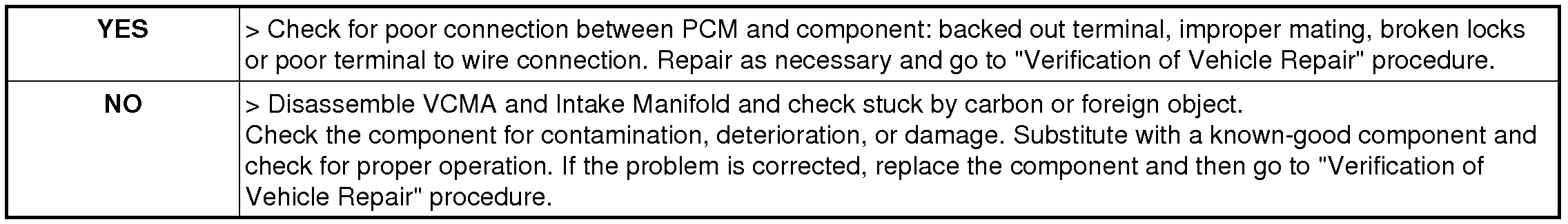
4. Is everything OK?
Picture 2
______________________________________
If you find it isn't working, the intake should be removed to clean and inspect the component. Yes, carbon can build up and cause it to stick. However, to fully access the component, it needs taken apart.
Here are the directions for removing the intake. Starting with picture 3, all pictures correlate with these directions.
_______________________________________________________________
REPAIR PROCEDURES
Removal
1. Disconnect the battery negative terminal.
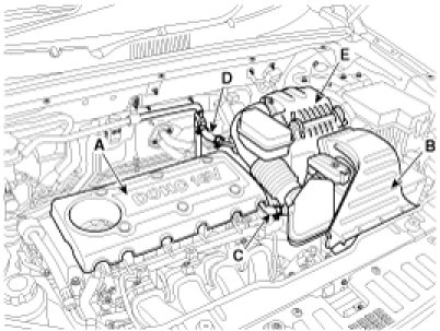
2. Remove the plastic engine cover (A).
3. Remove the air cleaner assembly.
(1)Remove the air duct (B).
(2)Disconnect the breather hose (C) and the intensifier hose (D).
(3)Disconnect the air intake hose and then remove the air cleaner assembly (E).
Tightening torque
Hose clamp bolt:
2.9 - 4.9N.m (0.3 - 0.5kgf.m, 2.2 - 3.6lb-ft)
Air cleaner assembly bolts:
7.8 - 9.8N.m (0.8 - 1.0kgf.m, 5.8 - 7.2lb-ft)
Picture 3
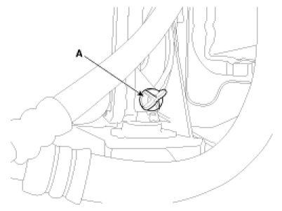
4. Loosen the drain plug (A), and drain the coolant. Remove the radiator cap to speed draining.
Picture 4 imageOpen In New TabZoom/Print
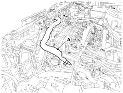
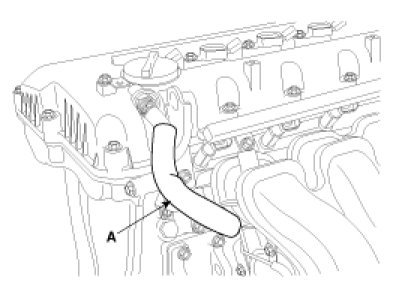
5. Remove the radiator upper hose (A).
Picture 5
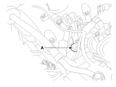
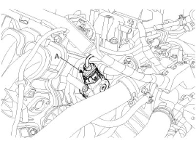
6. Disconnect the intake OCV (Oil control valve) connector (A).
Picture 6
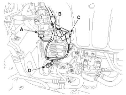
7. Disconnect the VIS (Variable intake system) connector (A), oil pressure switch connector (B), knock sensor connector (C) and the air compressor connector (D).
Picture 7
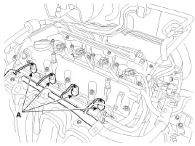
8. Disconnect the injector connectors (A).
Picture 8
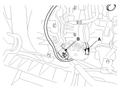
9. Disconnect the ETC (Electronic throttle control) connector (A) and MAPS (Manifold absolute pressure sensor) & IATS (Intake air temperature sensor) connector (B).
Picture 9
10. Disconnect the VCM (Variable charge motion) connector (A).
Picture 10
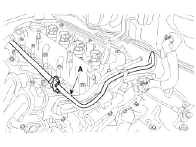
11. Disconnect the PCV (Positive crankcase ventilation) hose (A).
Picture 11
12. Disconnect the fuel hose (A).
Picture 12
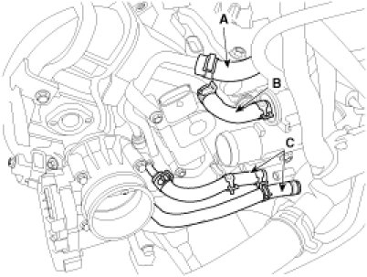
13. Disconnect the brake booster vacuum hose (A), PCSV (Purge control solenoid valve)hose (B) and throttle body coolant hoses (C).
Picture 13
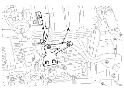
14. Disconnect the sensor connector from the bracket and remove the intake manifold stay (A).
Tightening torque :
18.6 - 23.5N.m (1.9 - 2.4kgf.m, 13.7 - 17.4lb-ft)
Picture 14
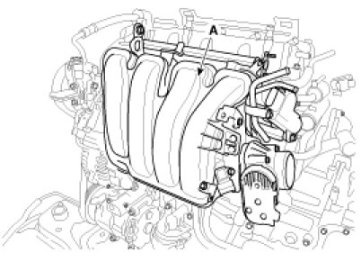
15. Remove the intake manifold (A).
Tightening torque :
Bolts & Nuts :
18.6 - 23.5N.m (1.9 - 2.4kgf.m, 13.7 - 17.4lb-ft)
Picture 15
16. Installation is reverse order of removal.
_______________________________________________
Let me know if this helps or if you have other questions.
Take care,
Joe
Images (Click to enlarge)
Feb 15, 2019 at 3:28 PM