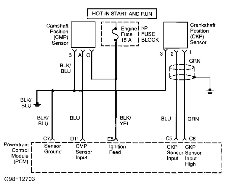
Only receiving 1.1 volts on the crankshaft position censor circuit. Why?

Tiny
SPAZZMODICUS
  • MEMBER
  • 1998 ISUZU AMIGO
  • 2.2L
  • 4 CYL
  • 2WD
  • MANUAL
  • 130,000 MILES
1998 Isuzu Amigo 2.2L

Only receiving 1.1 volts on the crankshaft position censor circuit, rather than the required 5 volts. Why?
On the CKP plug coming from the PCM, the ground terminal is good. On the other two terminals I only receive 1.1 volts. Best I can tell, that indicates a PCM problem. Also, I thought one of the three wires on the CKP sensor was supposed to be ground but I have no continuity with ground on the CKP sensor plug/harness.
Monday, March 31st, 2014 AT 9:50 AM

10 Replies

Tiny
HMAC300
  • MECHANIC
  • 48,601 POSTS
Here is how to check it see schematic as well.
Perform On-Board Diagnostic II (OBD-II) system check. See TESTS W/CODES-INTRODUCTION article. Go to next step.
Turn ignition off and disconnect CKP sensor. Turn ignition on. Connect DVOM between 5-volt reference and sensor ground terminals at connector harness. If DVOM reads 5 volts, go to step 5). If reading is not as specified, go to next step.
With ignition on, use DVOM to backprobe PCM connector reference and ground terminals. If DVOM reads 5 volts, go to next step. If reading is not as specified, go to step 9).
Using DVOM, check resistance at reference and ground circuits at CKP harness connector. If an open or short is discovered, repair circuit. Retest system.
Turn ignition off and disconnect PCM and CKP sensor. Check for an open or a short in 58X reference circuit between CKP sensor connector and PCM harness connector. If a problem is found, repair as necessary. Retest system. If no problem is found, go to next step.
Connect PCM and CKP sensor. Using DVOM, measure voltage on 58X reference circuit at PCM connector and crank engine. If reading on DVOM is about 2.5 volts, go to step 9). If voltage is not as specified, go to next step.
Inspect connections at CKP sensor. Repair connections as necessary. Retest system. If connections did not require repair, go to next step.
Replace CKP sensor. See COMPUTER RELEARN PROCEDURES article in GENERAL INFORMATION section. Retest system.
Inspect connections at PCM. Repair connections as necessary. Retest system. If connections did not require repair, go to next step.
Replace PCM. Program replacement PCM using required equipment. See COMPUTER RELEARN PROCEDURES article in GENERAL INFORMATION section. Retest system.
Check fuse as well in schematic.
Was this
answer
helpful?
Yes
No
+2
Monday, March 31st, 2014 AT 1:45 PM
Tiny
SPAZZMODICUS
  • MEMBER
  • 9 POSTS
Thanks for the quick reply. Back-probed the PCM ground and reference terminals: Got 1.2v. PCM replacement is necessary.

Ohming out the CKP sensor I get an open circuit. Should I see a particular resistance or does this mean the CKP sensor is bad as well? Wiring looks normal and undamaged, CKP sensor was working fine yesterday.

Could not find the suggested articles.

I did however forget to mention that as of late, the engine would only run with a cheap Centech(harbor freight) code reader plugged in. Unplug the reader, engine dies. Didn't matter if it was sitting still idling or going down the road at 55mph. I cleaned all grounds post PCM failure, but it did not help any. Too little, too late perhaps.

Thanks very much.
Was this
answer
helpful?
Yes
No
Monday, March 31st, 2014 AT 5:31 PM
Tiny
HMAC300
  • MECHANIC
  • 48,601 POSTS
Replace it to be safe that still may be the problem.
Was this
answer
helpful?
Yes
No
Tuesday, April 1st, 2014 AT 5:10 AM
Tiny
SPAZZMODICUS
  • MEMBER
  • 9 POSTS
Repaced the PCM with a used one which had the same identical 10 digit serial number. First thing I did was check for codes on the replacement PCM. They were long gone if there were any. Turned the key on and checked for reference voltage on the CKP harness. Only had 1.2v. That was.1v more than the old PCM. Backprobed the PCM, again only 1.2v. Decided to try to start it and it actually fired-up and ran, although a bit rough. Wouldn't even hit at all with the old PCM.

Additionally, I receive 5v on one terminal of the CMP harness and 7.3v on the other terminal of the CMP harness. Is there a chance that something in the wiring could be dragging the voltage down from the required 5v reference on both the CKP harness and PCM plug? (Terminals 5.6 &7?)
Was this
answer
helpful?
Yes
No
Wednesday, April 2nd, 2014 AT 3:49 PM
Tiny
HMAC300
  • MECHANIC
  • 48,601 POSTS
It could be a bad connector or a wire hitting someplace against the block or partially grounding out. Have you done the simple stuff like check the ecm main relay as that may not be supplying enough power to pcm to begin with. You should have battery voltage on one of the cmp connections so if it's not then there may be a short in harness or the ecm main relay isn't working very well and causing this. What were the original codes anyhow as you just started giving figures of voltage readings. Here is the way to check cam sensor power which you already have the pic I sent earlier if there is not up to snuff that is probably your problem but check the ecm main relay first.
Perform On-Board Diagnostic II (OBD-II) system check. See TESTS W/CODES-INTRODUCTION article. Go to next step.
Turn ignition on. Using scan tool, read and record FAILURE RECORDS data for DTC P0341. Operate vehicle within conditions noted in FAILURE RECORDS data. Using scan tool, read SPECIFIC DTC. If scan tool displays DTC P0341 FAILED THIS IGN, go to next step. If scan tool does not display DTC P0341 FAILED THIS IGN, see DIAGNOSTIC AIDS.
Using DVOM, backprobe PCM connector at CMP signal circuit. With sensor connected, crank engine and monitor voltage. If voltage toggles 0-4 volts, go to next step. If voltage does not toggle 0-4 volts, go to step 6).
Check for poor connection at PCM connector terminal D1. If a problem is found, repair as necessary. Retest system. If no problem is found, go to next step.
Replace PCM. Program replacement PCM using required equipment. See COMPUTER RELEARN PROCEDURES article in GENERAL INFORMATION section. Retest system.
Disconnect CMP sensor. Turn ignition on. Measure voltage at CMP sensor harness connector between sensor feed circuit and sensor ground circuit. If reading is about battery voltage, go to step 11). If reading is not as specified, go to next step.
Measure voltage between CMP positive connector at CMP sensor harness connector and ground. If reading is about battery voltage, go to step 9). If reading is not as specified, go to next step.
Repair open between PCM main relay and CMP sensor. Retest system.
Measure voltage between battery positive and CMP ground wire at CMP sensor harness connector. If reading is around battery voltage, go to step 11). If reading is not as specified, go to next step.
Repair open in ground circuit. Retest system.
Turn ignition off. Using DVOM, check continuity of signal wire between CMP sensor and PCM. If continuity does not exist, repair open signal wire. Retest system. If continuity exists, go to next step.
Turn ignition on. Check signal wire for short to ground or short to voltage. If problem is found, repair as necessary. Retest system. If no problem is found, go to next step
Was this
answer
helpful?
Yes
No
Wednesday, April 2nd, 2014 AT 4:13 PM
Tiny
SPAZZMODICUS
  • MEMBER
  • 9 POSTS
I simply gave the correct voltage I was receiving in the CMP harness as a comparison the the incorrect voltage I was receiving in the CKP harness. There are no problems in the CMP circuit. Part of the problem is that I have "NO CODES". It seems that the CKP circuit is malfunctioning and not generating a code.

I am receiving 12.3v on two terminals of the ECM relay and 3.9v on the third terminal of the same relay. Currently looking at the schematic to see if it should be more than 3.9v on the third terminal of the ECM relay.
Was this
answer
helpful?
Yes
No
Wednesday, April 2nd, 2014 AT 4:33 PM
Tiny
HMAC300
  • MECHANIC
  • 48,601 POSTS
I have no further suggestions.
Was this
answer
helpful?
Yes
No
Thursday, April 3rd, 2014 AT 5:47 AM
Tiny
SPAZZMODICUS
  • MEMBER
  • 9 POSTS
Again, for anybody else reading who may be having related problems: here are the "knowns" so far:

1998 Amigo 2.2L, 2WD, MT

1. PCM puts out 1.2v instead of the required 4.98v or 5v on two 'non-ground' pins of the CKP feed harness.

2. Pin C8 on the PCM connector is deader than a doorknob. No continuity with ground whatsoever. Any ground anywhere.

3. When back-probed at the PCM connector, the voltage to the 'non-ground' CKP pins is still 1.2v.

4. When the green H-5 connector below the brake fluid reservoir is unplugged, ( or what I believe to be the H-5. Not sure) and voltage read from the CKP pins of that connector, then the voltage jumps up to 7.1 volts.
5. When CKP pins are back-probed on the PCM connector with the H-4 connector disconnected, the voltage is still 7.1v.
6. The two wires responsible for the problem/voltage jump seems to be the black/blue and blue/red wires on the bottom of the H-4 connector. (Pins 13 & 14)
Was this
answer
helpful?
Yes
No
Saturday, April 26th, 2014 AT 6:32 AM
Tiny
ALAIN LEBRASSE
  • MEMBER
  • 5 POSTS
Hi everyone I am new here and I have a vw passat 1.9 tdi of 2002 and starting issue having 12volt at fuel pump but when cranking 0 volt to multimeter and also noticed receiving 2.5 volt on all 3 pins to crankshaft sensor any idea please?
Was this
answer
helpful?
Yes
No
Friday, April 12th, 2019 AT 11:16 AM
Tiny
KASEKENNY
  • MECHANIC
  • 18,907 POSTS
Hi Alain,

Welcome. I see you posted this to another post so I apologize for this taking a couple days to get back.

If you have 0 volts at the fuel pump when cranking then this is because your engine control module is shutting that circuit down so that it does not start. I would address you 2.5 volts on the crank sensor first. This is a three wire sensor so you should have a 5 volt reference circuit, a ground wire, and a signal wire. If all are the same then most likely the sensor is shorted.

Easiest way to see if the crank is sending a good signal to the engine controller is go to the coil. The engine controller will not send a signal to the coil if the crank is not reading properly. I am leading you to an ignition issue because I think this is your root cause for the no start. Here is a link to a video that is on a similar engine. However, you want to check your coil and see if it is firing as shown in the video. If not, then I would ohm out your wiring from the crank to the PCM and check it for a short to power, short to ground, and short together. If the wiring checks out then replace the crank sensor and retest. Once the coil is firing properly, recheck your fuel pump voltage when cranking. If I am correct, this should be back to battery voltage while cranking. As long as the ignition system is all hooked up and you have these items working as described, your vehicle should start.

Lastly, here are some documents that explain how to test the wiring so you can check out the wiring from the crank to PCM. Let me know if you have questions or update me once you make some progress. Thanks

https://youtu.be/X-uxkgveK7M

https://www.2carpros.com/articles/how-to-use-a-test-light-circuit-tester

https://www.2carpros.com/articles/how-to-use-a-voltmeter

https://www.2carpros.com/articles/how-to-check-wiring
Was this
answer
helpful?
Yes
No
Sunday, April 14th, 2019 AT 5:55 PM

Please login or register to post a reply.

Sponsored links