Before you take the oil pan off, I think I would try a different filter. Not saying the STP is the problem, but anything is possible. Also, did you use a mechanical gauge to check pressure? Is there any noise from the engine (ticking/knocking)?
If you decide to check the pump, here are the directions for removal and replacement. Not a fun job. All attached pictures correlate with the directions
OIL PUMP ASSEMBLY REPLACEMENT
imageOpen In New TabZoom/Print
imageOpen In New TabZoom/Print
imageOpen In New TabZoom/Print
imageOpen In New TabZoom/Print
imageOpen In New TabZoom/Print
imageOpen In New TabZoom/Print
imageOpen In New TabZoom/Print
imageOpen In New TabZoom/Print
OIL PUMP ASSEMBLY
REPLACEMENT
1. DRAIN ENGINE OIL
2. REMOVE FRONT WHEEL RH
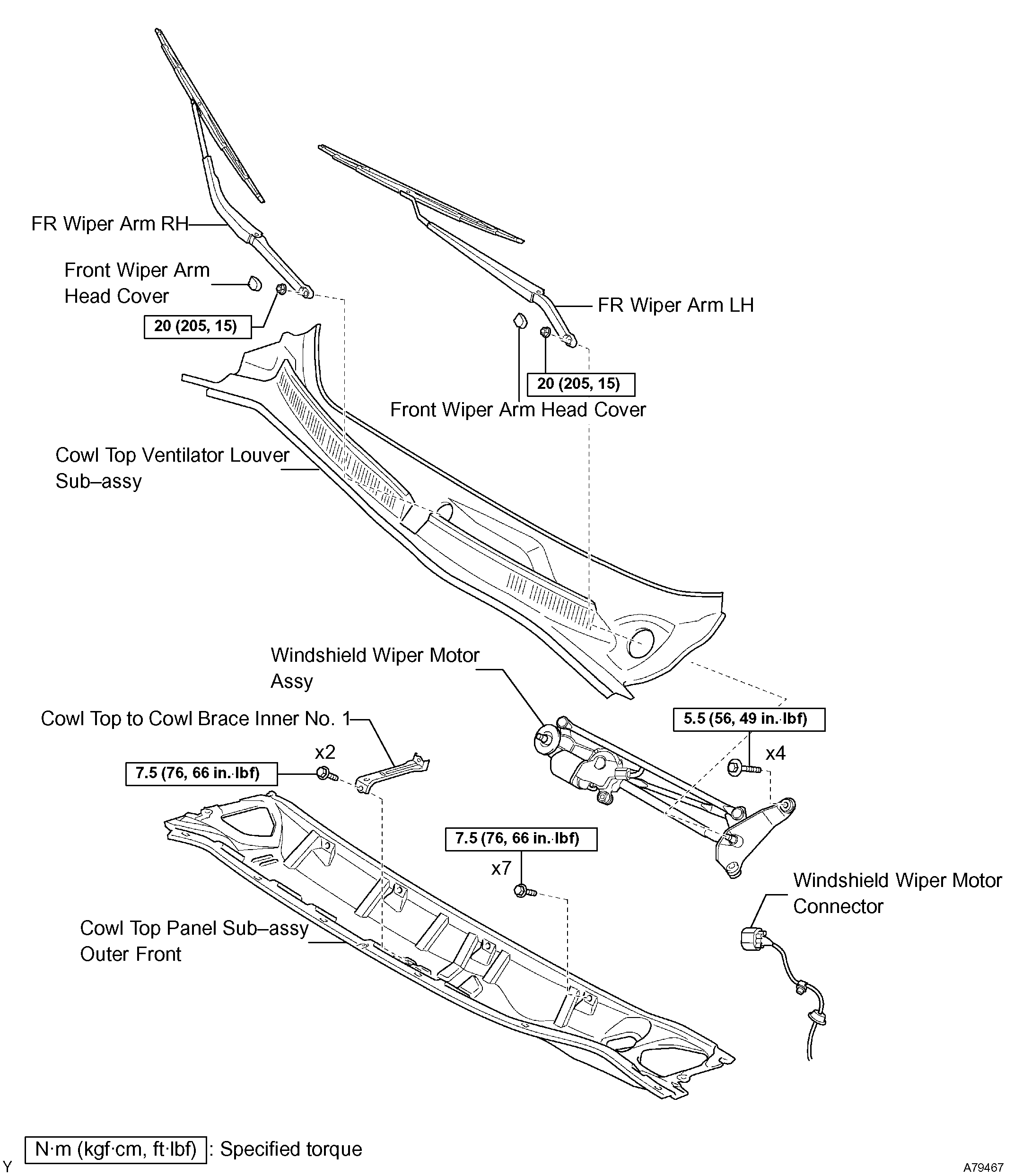
3. REMOVE FRONT WIPER ARM HEAD CAP
4. REMOVE FR WIPER ARM RH
5. REMOVE FR WIPER ARM LH
6. REMOVE COWL TOP VENTILATOR LOUVER SUB-ASSEMBLY
7. REMOVE WIPER LINK ASSEMBLY
8. REMOVE COWL TOP TO COWL BRACE INNER NO.1
9. REMOVE COWL TOP PANEL SUB-ASSEMBLY OUTER FRONT
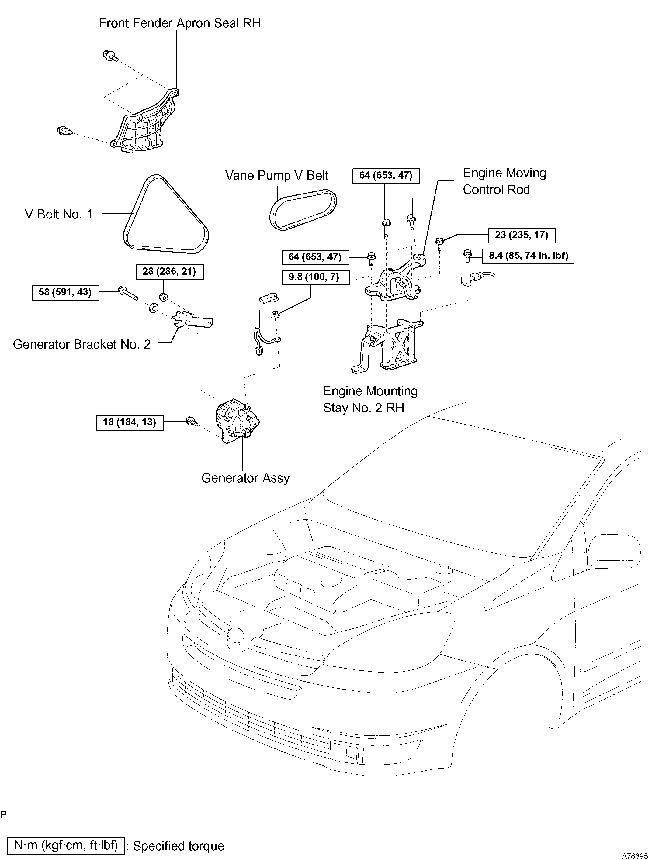
10. REMOVE FRONT FENDER APRON SEAL RH
11. REMOVE V (COOLER COMPRESSOR TO CRANKSHAFT PULLEY) BELT NO.1
12. REMOVE GENERATOR ASSEMBLY
13. REMOVE VANE PUMP V BELT
14. REMOVE ENGINE MOVING CONTROL ROD
15. REMOVE ENGINE MOUNTING STAY NO.2 RH
16. REMOVE GENERATOR BRACKET NO.2
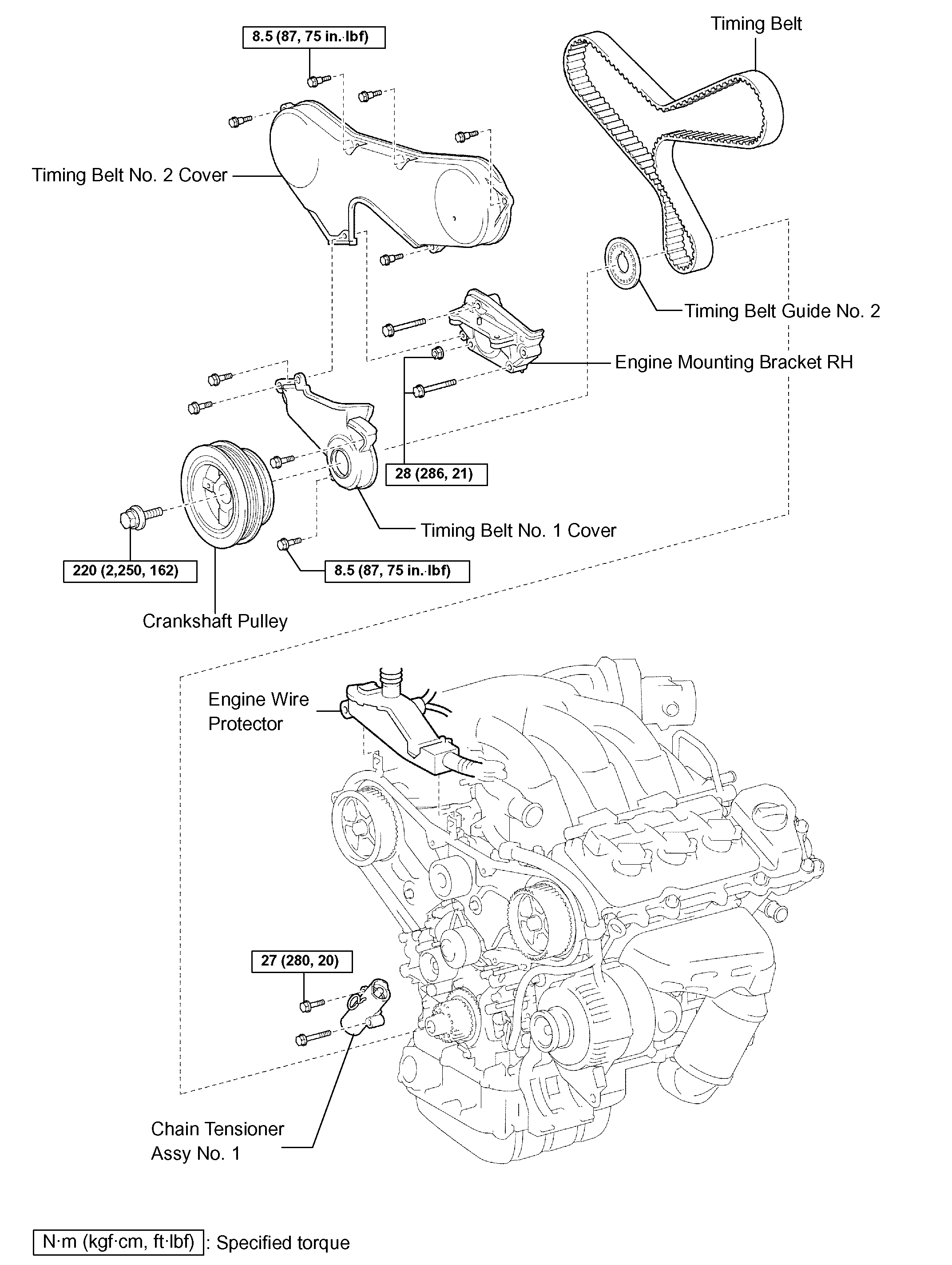
17. REMOVE CRANKSHAFT PULLEY
SST 09213-54015 (91651-60855), 09330-00021, 09950-50013 (09951-05010, 09952-05010, 09953-05020, 09954-05031)
18. REMOVE TIMING BELT NO.1 COVER
19. REMOVE TIMING BELT NO.2 COVER
20. REMOVE ENGINE MOUNTING BRACKET RH
21. REMOVE TIMING BELT GUIDE NO.2
22. REMOVE TIMING BELT
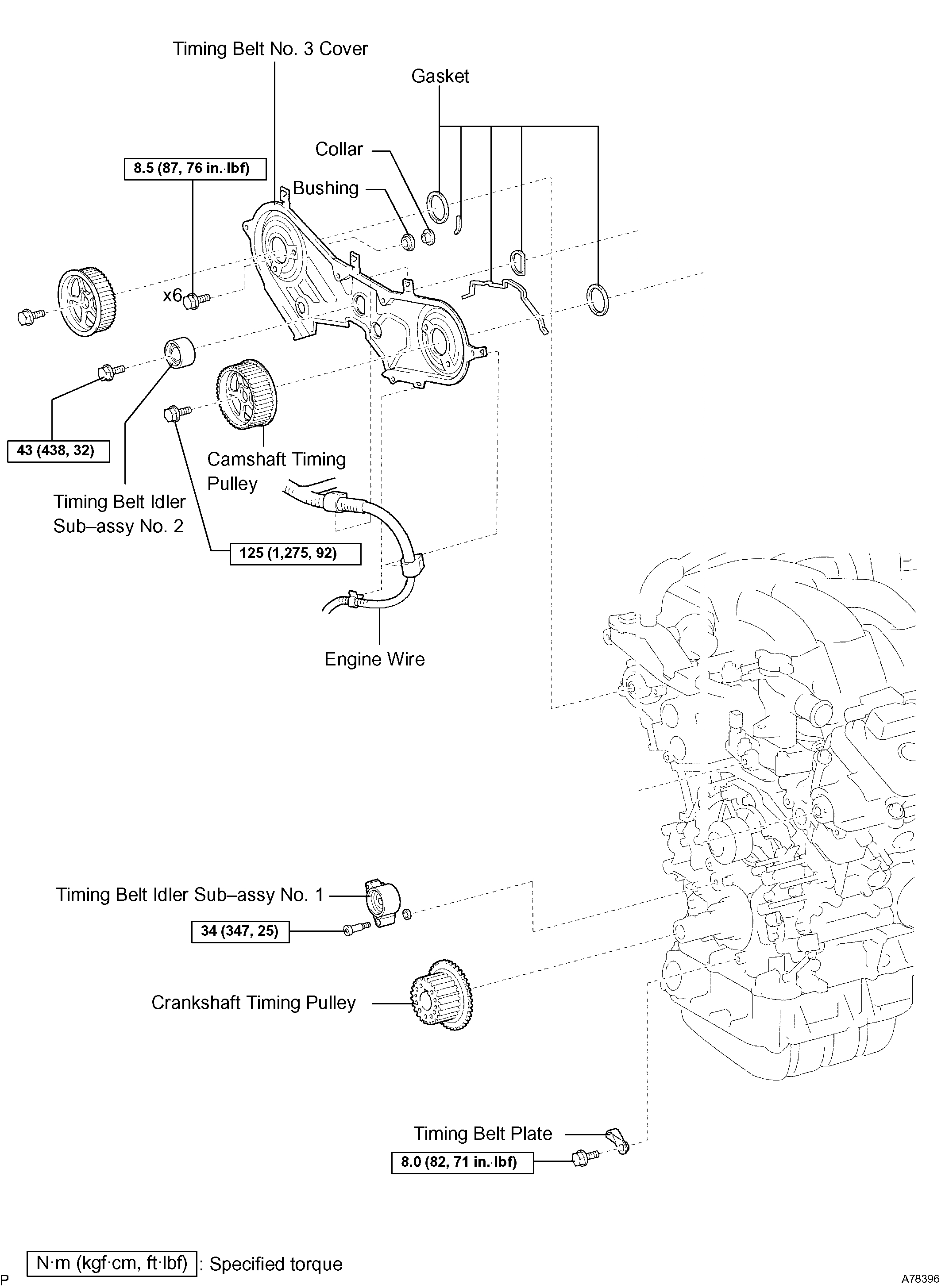
23. REMOVE TIMING BELT IDLER SUB-ASSEMBLY NO.2
24. REMOVE CAMSHAFT TIMING PULLEY
SST 09960-10010 (09962-01000, 09963-01000), 09249-63010
25. REMOVE TIMING BELT NO.3 COVER
26. REMOVE TIMING BELT IDLER SUB-ASSEMBLY NO.1
27. REMOVE CRANKSHAFT TIMING PULLEY
SST 09950-50013 (09951-05010, 09952-05010, 09953-05020, 09954-05011)
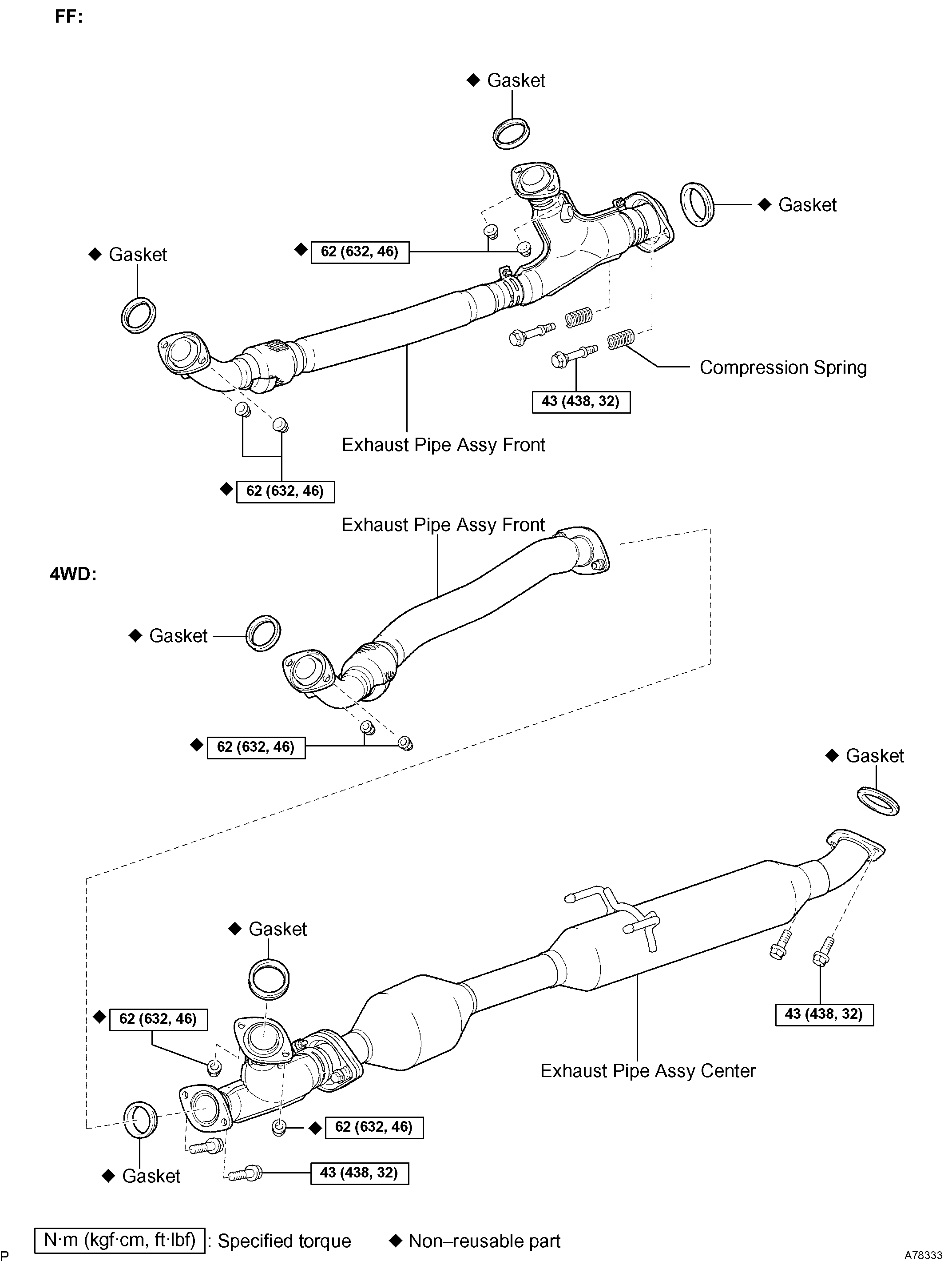
28. REMOVE EXHAUST PIPE ASSEMBLY CENTER (4WD DRIVE TYPE)
29. REMOVE EXHAUST PIPE ASSEMBLY FRONT (2WD DRIVE TYPE)
30. REMOVE EXHAUST PIPE ASSEMBLY FRONT (4WD DRIVE TYPE)
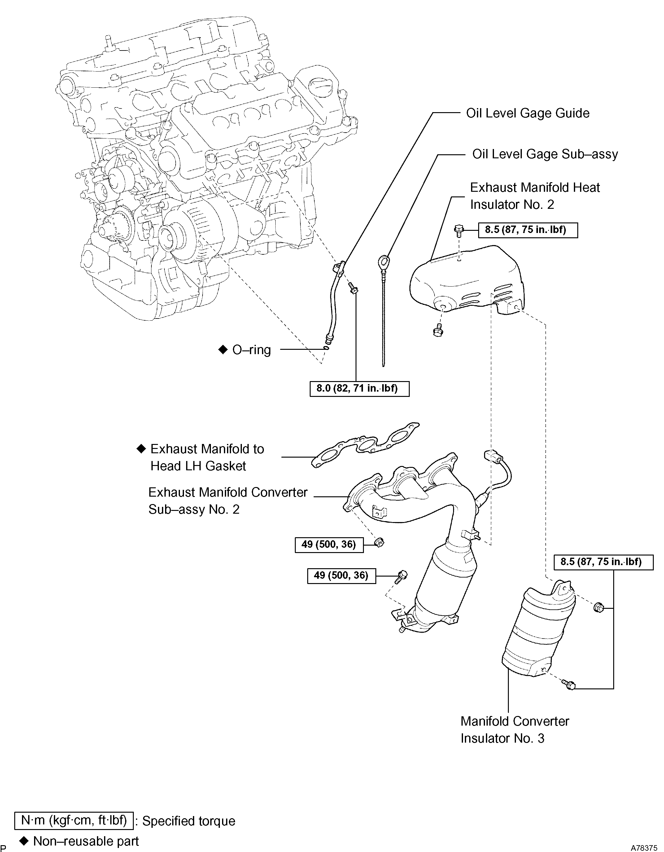
31. REMOVE MANIFOLD CONVERTER INSULATOR NO.3
32. REMOVE EXHAUST MANIFOLD HEAT INSULATOR NO.2
33. REMOVE EXHAUST MANIFOLD CONVERTER SUB-ASSEMBLY NO.2
34. REMOVE OIL LEVEL GAGE GUIDE
imageOpen In New TabZoom/Print
35. REMOVE GENERATOR BELT ADJUSTING BAR
a. Remove the 2 bolts, the 2 nuts and the adjusting bar.
ImageOpen In New TabZoom/Print
36. SEPARATE COMPRESSOR AND MAGNETIC CLUTCH
a. Disconnect the compressor connector.
B. Remove the 4 bolts, the adjusting bar bracket and the compressor.
HINT: The hoses are off to the side instead of detaching.
ImageOpen In New TabZoom/Print
37. REMOVE COMPRESSOR MOUNTING BRACKET NO.1
a. Remove the 2 bolts and the compressor mounting bracket No. 1.
ImageOpen In New TabZoom/Print
38. SEPARATE ENGINE MOUNTING INSULATOR RR (4WD DRIVE TYPE)
a. Remove the 2 nuts and disconnect the engine mounting insulator RR.
ImageOpen In New TabZoom/Print
39. SEPARATE ENGINE MOUNTING INSULATOR FR
a. Remove the 4 nuts and separate the engine mounting insulator FR.
NOTICE: Do not remove the engine mounting insulator FR.
ImageOpen In New TabZoom/Print
40. REMOVE ENGINE MOUNTING INSULATOR RH
a. Remove the bolt and disconnect the power steering return hose cramp from the frame.
B. Remove the 4 nuts.
C. Place a wooden block on a jack underneath the engine.
D. Jack-up the engine and remove the engine mounting insulator RH.
NOTICE: Be careful not to damage the oil pan.
ImageOpen In New TabZoom/Print
41. REMOVE ENGINE MOUNTING BRACKET RH
a. Remove the 4 bolts, the nut and the bracket.
42. REMOVE OIL PAN SUB-ASSEMBLY NO.2
imageOpen In New TabZoom/Print
a. Remove the 10 bolts and the 2 nuts.
ImageOpen In New TabZoom/Print
b. Insert the blade of SST between oil pan No.1 and oil pan No.2, cut off the sealer and remove the oil pan No.2.
SST 09032-00100
NOTICE:
Be careful not to damage the contact surface of oil pan No. 1 where oil pan No. 2 is mounting.
Do not damage flange portion of oil pan No. 2 when removing.
43. REMOVE OIL STRAINER SUB-ASSEMBLY
a. Remove the bolt, the 2 nuts, the oil strainer and the gasket.
44. REMOVE OIL PAN SUB-ASSEMBLY
imageOpen In New TabZoom/Print
a. Remove the 2 bolts and the flywheel housing under cover.
ImageOpen In New TabZoom/Print
b. Loosen and remove the 17 bolts and the 2 nuts uniformly.
ImageOpen In New TabZoom/Print
c. Using a screwdriver, remove the oil pan by prying between the cylinder block and the oil pan.
NOTICE: Be careful not to damage the contact surfaces of the oil pan and cylinder block.
45. REMOVE CRANKSHAFT POSITION SENSOR
a. Disconnect the crankshaft position sensor connector.
B. Remove the bolt and the crankshaft position sensor.
ImageOpen In New TabZoom/Print
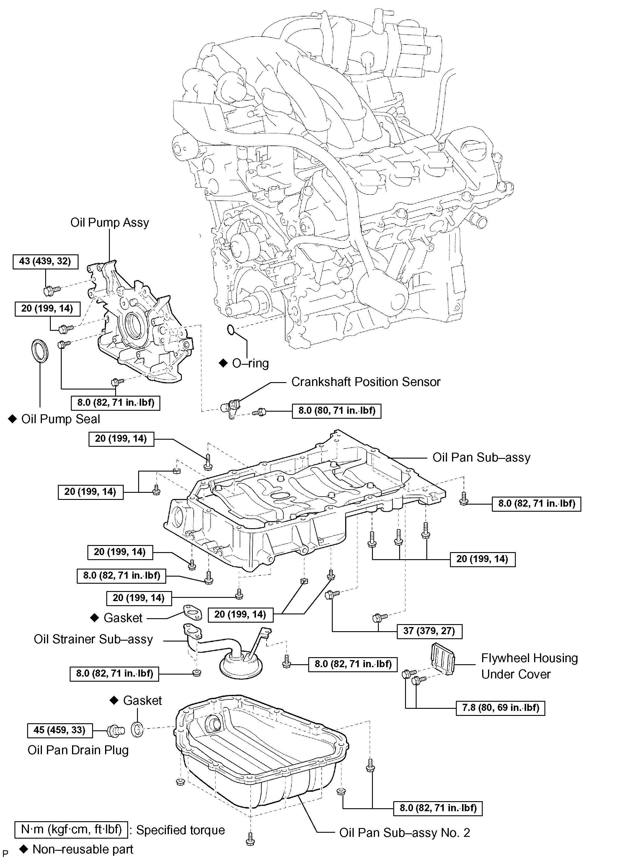
46. REMOVE OIL PUMP ASSEMBLY
a. Remove the 9 bolts.
B. Using a screwdriver, remove the oil pump by prying between the oil pump and the main bearing cap.
C. Remove the O-ring.
ImageOpen In New TabZoom/Print
47. INSTALL OIL PUMP SEAL
a. Using SST and a hammer, tap in a new oil seal until its surface is flush with the oil pump body edge.
SST 09223-00010
NOTICE:
Be careful not to tap the oil seal at an angle.
Keep the lip free of foreign objects.
B. Apply MP grease to the oil seal lip.
48. INSTALL OIL PUMP ASSEMBLY
a. Remove any old seal packing material from the contact surface.
ImageOpen In New TabZoom/Print
b. Apply a light coat of engine oil to a new O-ring and place it on the cylinder block.
ImageOpen In New TabZoom/Print
c. Apply a continuous bead of seal packing (Diameter 2 to 3 mm (0.08 to 0.12 inch)) as shown in the illustration.
Seal packing: Part No. 08826-00080 or equivalent
NOTICE:
Remove any oil from contact surface.
Apply seal packing to the inner side of the bolt holes.
Install the oil pump within 3 minutes after applying seal packing.
Do not expose the seal to engine oil within 2 hours after installing.
ImageOpen In New TabZoom/Print
d. Align the key of the oil pump drive gear with the keyway located on the crankshaft, and slide the oil pump into place.
ImageOpen In New TabZoom/Print
e. Install the oil pump with the 9 bolts. Tighten the bolts uniformly in several steps.
Torque:
Bolt A 8.0 Nm (82 kgf-cm, 71 inch lbs.)
Bolt B 20 Nm (199 kgf-cm, 14 ft. Lbs.)
Bolt C 43 Nm (439 kgf-cm, 32 ft. Lbs.)
49. INSTALL CRANKSHAFT POSITION SENSOR
Torque: 8.0 Nm (80 kgf-cm, 71 inch lbs.)
imageOpen In New TabZoom/Print
50. INSTALL OIL PAN SUB-ASSEMBLY
a. Remove any old seal packing from the contact surface.
B. Apply a continuous bead of seal packing (Diameter 3 to 4 mm (0.12 to 0.16 inch)) as shown in the illustration.
Seal packing: Part No. 08826-00080 or equivalent
NOTICE:
Remove any oil from the contact surface.
Apply seal packing to the outer side of the bolt holes in the region "X".
Apply seal packing to the inner side of the bolt holes in the region "Y".
Install the oil pan within 3 minutes after applying seal packing.
Do not expose the seal to engine oil within 2 hours after installing.
C. Install the oil pan No.1 with the 17 bolts and the 2 nuts. Tighten the bolts uniformly in several steps.
Torque:
10 mm head 8.0 Nm (82 kgf-cm, 71 inch lbs.)
12 mm head 20 Nm (199 kgf-cm, 14 ft. Lbs.)
14 mm head 37 Nm (379 kgf-cm, 27 ft. Lbs.)
c. Install the flywheel housing under cover with the 2 bolts.
Torque: 7.8 Nm (80 kgf-cm, 69 inch lbs.)
51. INSTALL OIL STRAINER SUB-ASSEMBLY
a. Install a new gasket and the oil strainer with the bolt and the 2 nuts.
Torque: 8.0 Nm (82 kgf-cm, 71 inch lbs.)
imageOpen In New TabZoom/Print
52. INSTALL OIL PAN SUB-ASSEMBLY NO.2
a. Remove any old seal packing from the contact surface.
B. Apply a continuous bead of seal packing (Diameter 4 to 5 mm (0.16 to 0.20 inch)) as shown in the illustration.
Seal packing: Part No. 08826-00080 or equivalent
NOTICE:
Remove any oil from the contact surface.
Apply seal packing to the inner side of the bolt holes.
Install the oil pan within 3 minutes after applying seal packing.
Do not expose the seal to engine oil within 2 hours after installing.
C. Install the oil pan No. 2 with the 10 bolts and the 2 nuts.
Torque: 8.0 Nm (82 kgf-cm, 71 inch lbs.)
imageOpen In New TabZoom/Print
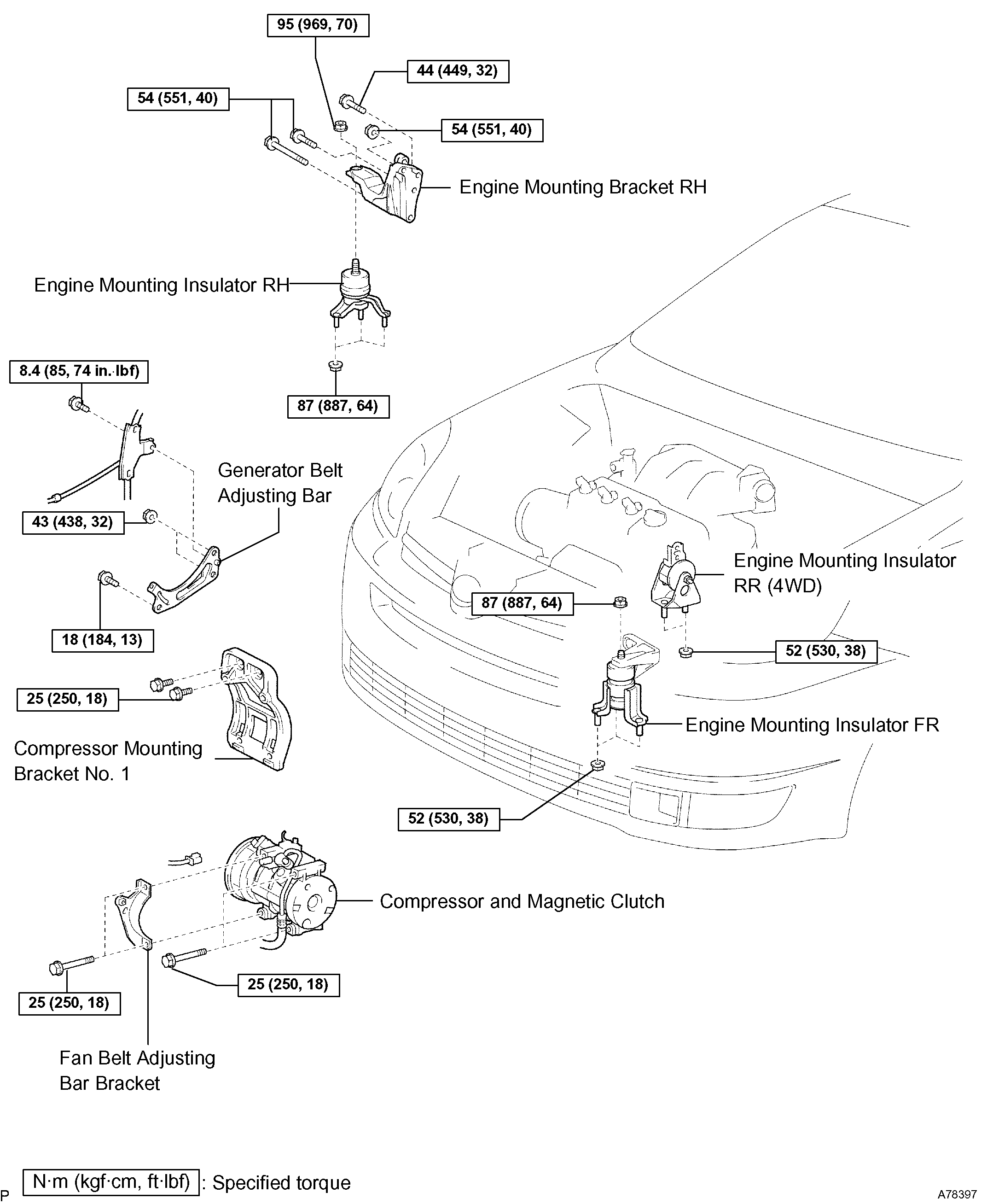
53. INSTALL ENGINE MOUNTING BRACKET RH
Torque:
Bolt A 54 Nm (551 kgf-cm, 40 ft. Lbs.)
Nut B 54 Nm (551 kgf-cm, 40 ft. Lbs.)
Bolt C 44 Nm (449 kgf-cm, 32 ft. Lbs.)
imageOpen In New TabZoom/Print
54. INSTALL ENGINE MOUNTING INSULATOR RH
Torque:
Nut A 95 Nm (969 kgf-cm, 70 ft. Lbs.)
Nut B 87 Nm (887 kgf-cm, 64 ft. Lbs.)
imageOpen In New TabZoom/Print
55. INSTALL ENGINE MOUNTING INSULATOR FR
Torque:
Nut A 87 Nm (887 kgf-cm, 64 ft. Lbs.)
Nut B 52 Nm (530 kgf-cm, 38 ft. Lbs.)
imageOpen In New TabZoom/Print
56. INSTALL ENGINE MOUNTING INSULATOR RR (4WD DRIVE TYPE)
Torque: 52 Nm (530 kgf-cm, 38 ft. Lbs.)
57. INSTALL COMPRESSOR MOUNTING BRACKET NO.1
Torque: 25 Nm (250 kgf-cm, 18 ft. Lbs.)
imageOpen In New TabZoom/Print
58. INSTALL COMPRESSOR AND MAGNETIC CLUTCH
a. Install the compressor and the adjusting bar bracket with the 4 bolts.
Torque: 25 Nm (250 kgf-cm, 18 ft. Lbs.)
imageOpen In New TabZoom/Print
59. INSTALL GENERATOR BELT ADJUSTING BAR
a. Install the adjusting bar with the 2 bolts and the 2 nuts.
Torque:
Nut A 43 Nm (438 kgf-cm, 32 ft. Lbs.)
Bolt B 18 Nm (184 kgf-cm, 13 ft. Lbs.)
Bolt C 8.4 Nm (85 kgf-cm, 74 inch lbs.)
60. INSTALL OIL LEVEL GAGE GUIDE
61. INSTALL EXHAUST MANIFOLD CONVERTER SUB-ASSEMBLY NO.2
62. INSTALL EXHAUST MANIFOLD HEAT INSULATOR NO.2
63. INSTALL MANIFOLD CONVERTER INSULATOR NO.3
64. INSTALL EXHAUST PIPE ASSEMBLY FRONT (2WD DRIVE TYPE)
65. INSTALL EXHAUST PIPE ASSEMBLY FRONT (4WD DRIVE TYPE)
66. INSTALL EXHAUST PIPE ASSEMBLY CENTER (4WD DRIVE TYPE)
67. INSTALL CRANKSHAFT TIMING PULLEY
68. INSTALL TIMING BELT IDLER SUB-ASSEMBLY NO.1
69. INSTALL TIMING BELT NO.3 COVER
70. INSTALL CAMSHAFT TIMING PULLEY
SST 09960-10010 (09962-01000, 09963-01000), 09249-63010
71. INSTALL TIMING BELT IDLER SUB-ASSEMBLY NO.2
72. INSPECT TIMING BELT
73. INSTALL TIMING BELT
SST 09960-10010 (09962-01000, 09963-01000)
74. INSTALL CHAIN TENSIONER ASSEMBLY NO.1
75. INSTALL TIMING BELT GUIDE NO.2
76. INSTALL ENGINE MOUNTING BRACKET RH
77. INSTALL TIMING BELT NO.2 COVER
78. INSTALL TIMING BELT NO.1 COVER
79. INSTALL CRANKSHAFT PULLEY
SST 09213-54015 (91651-60855), 09330-00021
80. INSTALL GENERATOR BRACKET NO.2
81. INSTALL ENGINE MOUNTING STAY NO.2 RH
82. INSTALL ENGINE MOVING CONTROL ROD
83. INSTALL VANE PUMP V BELT
84. INSTALL GENERATOR ASSEMBLY
85. INSTALL V (COOLER COMPRESSOR TO CRANKSHAFT PULLEY) BELT NO.1
86. INSPECT DRIVE BELT DEFLECTION AND TENSION (REFERENCE)
87. INSTALL COWL TOP PANEL SUB-ASSEMBLY OUTER FRONT
88. INSTALL COWL TOP TO COWL BRACE INNER NO.1
89. INSTALL WIPER LINK ASSEMBLY
90. INSTALL FR WIPER ARM LH
91. INSTALL FR WIPER ARM RH
92. INSTALL FRONT WHEEL RH
93. ADD ENGINE OIL
94. CHECK FOR ENGINE OIL LEAKS
95. CHECK FOR EXHAUST GAS LEAKS
Let me know.
Joe
Images (Click to make bigger)
Monday, May 20th, 2019 AT 7:41 PM