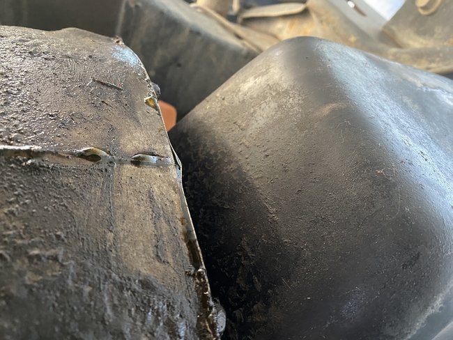
Okay, this could be from either the back of the intake manifold or the rear main oil seal.
Get a good look at the back of the intake to see if it is leaking down the back.
https://www.2carpros.com/articles/replace-intake-manifold-gasket
Roy
REMOVAL
1. Remove the oil pan.
2. Remove the oil pump from the rear main bearing cap.
3. Remove the rear main bearing cap and discard the old lower seal.
INSTALLATION
1. Clean the rear main cap mating surfaces including the oil pan gasket groove.
2. Carefully install a new upper seal.
3. Lightly oil the new lower seal lips with engine oil.
4. Install a new lower seal in bearing cap with the white paint facing the rear of engine.
Sealant Application To Bearing Cap
imageOpen In New TabZoom/Print
5. Apply 5 mm (0.20 inch) drop of Loctite 518, or equivalent, on each side of the rear main bearing cap. DO NOT over apply sealant or allow the sealant to contact the rubber seal. Assemble bearing cap to cylinder block immediately after sealant application.
6. To align the bearing cap, use cap slot, alignment dowel and cap bolts. DO NOT remove excess material after assembly. DO NOT strike rear cap more than 2 times for proper engagement.
7. Install the rear main bearing cap with cleaned and oiled cap bolts. Alternately tighten the cap bolts to 115 Nm (85 ft. lbs.) torque.
8. Install oil pump.
Apply Sealant To Bearing Cap To Block Joint
imageOpen In New TabZoom/Print
9. Apply Mopar Silicone Rubber Adhesive Sealant, or equivalent, at bearing cap to block joint to provide cap to block and oil pan sealing. Apply enough sealant until a small amount is squeezed out. Withdraw nozzle and wipe excess sealant off the oil pan seal groove.
10. Immediately install the oil pan.
Intake manifold
REMOVAL
1. Disconnect the negative cable from the battery.
2. Drain the cooling system.
3. Remove the generator.
4. Remove the air cleaner.
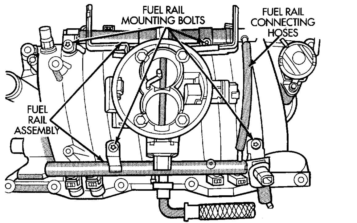
5. Perform the Fuel System Pressure release procedure. Disconnect the fuel lines.
6. Disconnect the accelerator linkage and if so equipped, the speed control and transmission kickdown cables.
7. Remove the return spring.
8. Remove the distributor cap and wires.
9. Disconnect the coil wires.
10. Disconnect the heat indicator sending unit wire.
11. Disconnect the heater hoses and bypass hose.
12. Remove the closed crankcase ventilation and evaporation control systems.
13. Remove intake manifold bolts.
14. Lift the intake manifold and throttle body out of the engine compartment as an assembly.
15. Remove and discard the flange side gaskets and the front and rear cross-over gaskets.
Throttle Body Assembly
imageOpen In New TabZoom/Print
16. Remove the throttle body bolts and lift the throttle body off the intake manifold. Discard the gasket.
17. Remove the plenum pan as follows:
(a)Turn the intake manifold upside down. Support the manifold.
(b)Remove the bolts and lift the pan off the manifold. Discard the gasket.
INSTALLATION
1. Install the plenum pan, if removed, as follows:
(a)Turn the intake manifold upside down. Support the manifold.
(b)Place a new plenum pan gasket onto the seal rail of the intake manifold. Position the pan over the gasket. Align all the gasket and pan holes with the intake manifold.
(c)Hand start all bolts.
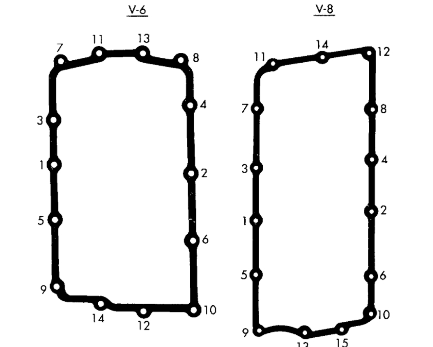
Plenum Pan Bolt Tightening Sequence
imageOpen In New TabZoom/Print
(d)Tighten the bolts, in sequence, as follows:
- Step 1-Tighten bolts to 2.7 Nm (24 inch lbs.) torque.
- Step 2-Tighten bolts to 5.4 Nm (48 inch lbs.) torque.
- Step 3-Tighten bolts to 9.5 Nm (84 inch lbs.) torque.
- Step 4-Check that all bolts are tighten to 9.5 Nm (84 inch lbs.) torque.
2. Using a new gasket, install the throttle body onto the intake manifold. Tighten the bolts to 23 Nm (200 inch lbs.) torque.
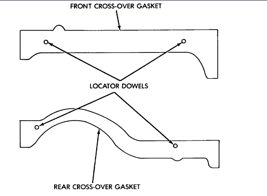
Cross-Over Gaskets And Locator Dowels
imageOpen In New TabZoom/Print
3. Place the 4 plastic locator dowels into the holes in the block.
4. Apply Mopers Silicone Rubber Adhesive Sealant, or equivalent, to the four corner joints. An excessive amount of sealant is not required to ensure a leak proof seal. However, an excessive amount of sealant may reduce the effectiveness of the flange gasket. The sealant should be slightly higher than the cross-over gaskets, approximately 5 mm (0.2 inch).
5. Install the front and rear cross-over gaskets onto the dowels.
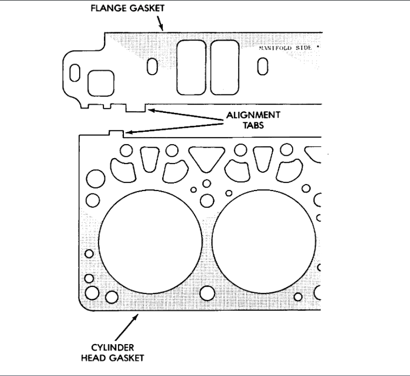
Intake Manifold Flange Gasket Alignment
imageOpen In New TabZoom/Print
6. Install the flange gaskets. Ensure that the vertical port alignment tab is resting on the deck face of the block. Also the horizontal alignment tabs must be in position with the mating cylinder head gasket tabs. The words MANIFOLD SIDE should be visible on the center of each flange gasket.
7. Carefully lower intake manifold into position on the cylinder block and cylinder heads. Use the alignment dowels in the cross-over gaskets to position the intake manifold. After intake manifold is in place, inspect to make sure seals are in place.
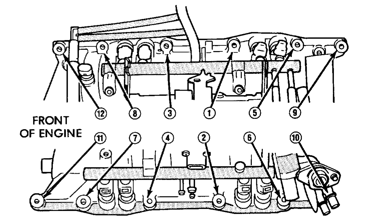
Intake Manifold Bolt Tightening Sequence-V-8
imageOpen In New TabZoom/Print
8. Install the intake manifold bolts and tighten as follows:
- Step 1-Tighten bolts 1 through 4, in sequence, to 8 Nm (72 inch lbs.) torque. Tighten. in alternating steps 1.4 Nm (12 inch lbs.) torque at a time.
- Step 2-Tighten bolts 5 through 12, in sequence, to 8 Nm (72 inch lbs.) torque.
- Step 3-Check that all bolts are tighten to 8 Nm (72 inch lbs.) torque.
- Step 4-Tighten all bolts, in sequence, to 16 Nm (12 ft. lbs.) torque.
- Step 5-Check that all bolts art tighten to 16 Nm (12 ft. lbs.) torque.
9. Install closed crankcase ventilation and evaporation control systems.
10. Connect the coil wires.
11. Connect the heat indicator sending unit wire.
12. Connect the heater hoses and bypass hose.
13. Install distributor cap and wires.
14. Hook up the return spring.
15. Connect the accelerator linkage and if so equipped, the speed control and transmission kickdown cables.
16. Install the fuel lines.
17. Install the generator and drive belt. Tighten generator mounting bolt to 41 Nm (30 ft. lbs.) torque.
18. Install the air cleaner.
19. Fill cooling system.
20. Connect the negative cable to the battery.
Images (Click to enlarge)
Mar 16, 2021 at 3:43 AM