Does not stay running after removing jumper cables?

Tiny
JUDIE_SIMMONS
  • MEMBER
  • 2005 HYUNDAI ELANTRA
  • 2.0L
  • 4 CYL
  • 2WD
  • AUTOMATIC
  • 245,270 MILES
The car will start when attached to the jumper cables but when they are removed the car shuts off. The battery and the alternator work according to AutoZone so I don't know what to do next. I'm trying to troubleshoot this issue for my family member car.
Thursday, March 2nd, 2023 AT 9:15 AM

8 Replies

Tiny
CARADIODOC
  • MECHANIC
  • 33,748 POSTS
Dandy reply, but please allow me to add a few comments of value. Normally I would say the worst way to test a generator is off the engine because that testing doesn't include the vehicle's wiring and in many cases the voltage regulator. Bench testers also aren't strong enough to drive generators to their maximum output capacity, and they don't check for "ripple" voltage.

This case is different in that the charging system can't be tested because the engine stalls. You eluded to the fact that jumper cables needed to be connected, but to continue the thought, that means it was the donor car that was under test.

The first thing to consider is the battery is totally discharged. When that happens, it can take a good 15 minutes before it starts to take a charge. It can take that long for the acid to become conductive, then the electrons begin to get absorbed into the plates. If you use a small portable charger on a low rate, you'll see the meter indicate near 0 amps for that first 15 minutes, then it will slowly start to rise. After a few hours, the battery can be considered to be fully-charged when the current drops below around 5 amps.

The next problem has to do with how the voltage regulator works. That varies between brands and models. Some will see the low battery voltage when the jumper cables are disconnected, and respond by shutting down. That means no output from the generator, so the engine stalls. On other models, the voltage regulator will get up and running with the jump start, then once they're disconnected, the regulator will see the low battery voltage, and make the generator run harder to produce higher voltage and more output current. I'll add one more comment related to this later.

The next problem has to do with the "diodes" in all "AC Generators". (We all know what is meant by the word "alternator", but to be technically correct in the classroom, that is a Chrysler term. They developed the alternator for 1960 models and copyrighted the term). For the rest of us, the industry refers to them as "AC generators". Regardless, they all have at least six diodes which are one-way valves for electrical current flow. Generators put out three-phase output current which is very stable and efficient. The point of this sad story is if one diode fails, you'll lose one of those three phases, and the generator will lose exactly two thirds of its current-generating capacity. The standard generator for this model is a 90-amp unit. That means with a failed diode, all it will be able to develop is close to 30 amps. That's not enough to meet the demands of the entire electrical system under all conditions. The battery will have to make up the difference as it slowly runs down over days or weeks. If the battery is already run down, there won't be enough output from the generator to run the vehicle even if the voltage regulator did start up.

To add to the confusion, this is where a generator with a bad diode can still test "good" on a test bench. It takes about a one horsepower motor to run a generator supplying 30 amps on a test bench. To get full output from a properly working generator takes closer to five horsepower. Bench testers don't have electric motors that big.

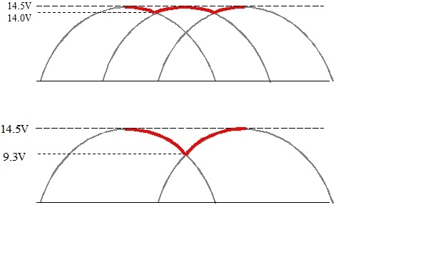
"Ripple" voltage refers to the unsteady output voltage, as shown in my first drawing. This generator will develop up to 90 amps with all good diodes, and ripple voltage for this example is shown as 0.5 volts, (red section). Below that, one phase is missing. Here again, the red section shows the output voltage that will be developed. Ripple voltage is 5.2 volts.

Professional load testers test charging systems on the car by measuring maximum output current and ripple voltage. Both are indications as to the condition of the diodes. A few testers that can make paper printouts will list an actual voltage for ripple voltage, but most testers just show it on a relative bar chart as "low" or "high".

The bottom line is bench testers don't measure ripple voltage and they aren't strong enough to drive a generator to its full output current capacity, so they can't show if the diodes are all good or not. This goes back to which way a voltage regulator works. Some will look at the low points in the output voltage, (9.3 volts in the lower drawing), and respond by bumping up the charging voltage. Some will look at the highest point, (14.5 volts), and cut back on generator output, often, again, to the point of stalling.

All of this should be eliminated by getting the battery fully charged first. Once that is done, this article explains how to start the charging system test:

https://www.2carpros.com/articles/how-to-check-a-car-alternator

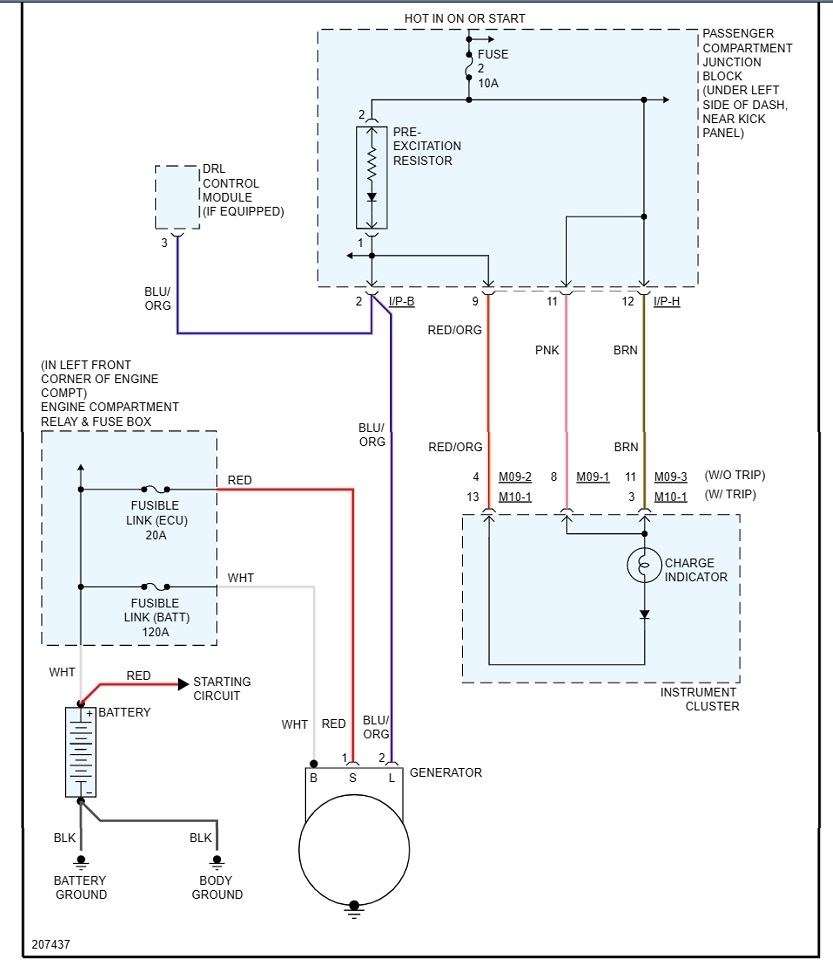
Doing this on the car includes the system voltage sensing circuit and the generator's output circuit. There's actually three different circuits that can cause a good generator to not work. If this charging voltage test is okay, it only means it is okay to continue with the rest of the tests, but those require the professional load tester.

I know that's a lot of information with not a definite answer. Let us know how you'd like to proceed or if you have more questions.
Was this
answer
helpful?
Yes
No
Thursday, March 2nd, 2023 AT 7:21 PM
Tiny
CARADIODOC
  • MECHANIC
  • 33,748 POSTS
Hi JUDIE_SIMMONS. There was a previous reply that got deleted while I was preparing mine. Take that into account when some of my comments refer to that or don't seem to make sense. Again, let me know if this helps or if you have other questions.
Was this
answer
helpful?
Yes
No
Thursday, March 2nd, 2023 AT 7:24 PM
Tiny
JUDIE_SIMMONS
  • MEMBER
  • 57 POSTS
What is the High Middle Low voltage level that will show if the voltage regulator is working properly or needs replacing and what is the acceptable voltage?
Was this
answer
helpful?
Yes
No
Friday, March 3rd, 2023 AT 12:31 AM
Tiny
JUDIE_SIMMONS
  • MEMBER
  • 57 POSTS
Can I get the proper diagram and information for the 05 Hyundai Elantra GLS the 8th - D - 2.0 DOHC V16 4Cylinder Automatic?
Was this
answer
helpful?
Yes
No
Friday, March 3rd, 2023 AT 12:39 AM
Tiny
CARADIODOC
  • MECHANIC
  • 33,748 POSTS
The acceptable range of charging voltage varies a little depending on which textbook you read, but for my stories, I want to see between 13.75 and 14.75 volts. Lower than that and the battery will not get fully charged. Too much higher than that and the water will start to boil out of the battery's acid.

The first step is to measure the battery's voltage with the engine off. It will be very close to 12.6 volts if it's good and fully-charged. If you find it's closer to 12.2 volts, it's good but fully-discharged. It should be charged for a couple of hours at a slow rate with a portable charger before continuing. If you find it's around 11 volts, it has a shorted cell and must be replaced.

Next, measure the voltage again with the engine running. If it's just a little low, see if it rises when engine speed is increased a little. All generators are very inefficient at low speeds. Professional testers require engine speed to be increased to 2,000 rpm during the few seconds these tests take.

This one quick test shows if the voltage regulator is working properly. That is the test being done in this article:

https://www.2carpros.com/articles/how-to-check-a-car-alternator

You can also expect the voltage to be on the low side if the battery is badly run down. When that happens, the system voltage will rise gradually as the battery charges up. This is the only test you can do yourself. When there are no other symptoms, passing this test is all you need to care about. There's no need to go further.

If this charging voltage test passes, but there are other symptoms, it only means it is okay to perform the rest of the tests, but that requires the professional load tester. Mine has seven LEDs stacked in a vertical column to show ripple voltage. If it's low, meaning normal or acceptable, only the one or two lowest bulbs will be flickering. If it's high, all six or seven will be lit up. Those are the only two choices. There is not an actual voltage given. In my previous reply, my drawings were only for explanation purposes. We don't actually see those waveforms on the tester.

If you can read this diagram, I'm guessing you know how to use a digital voltmeter, but for the benefit of others researching this topic, this article explains it better:

https://www.2carpros.com/articles/how-to-use-a-voltmeter

They're using an "auto-ranging" meter which is an expensive feature that isn't needed. You can find a perfectly fine meter at Harbor Freight Tools for around $7.00. Also look at Walmart or any hardware store. I can help with setting it up if necessary.

The first step in diagnosing this system is to observe if the "Battery" warning light on the instrument cluster turns on when the ignition switch is turned to "run". If it does not, the blue / orange wire likely has a break. Next, measure the voltage on that wire at the generator's plug, (blue arrow in the third diagram). To be valid, these next two readings must be taken with the connector plugged in. Back-probe alongside the wires to take the readings. Expect to find very close to 2.0 volts. That says the warning light will be on, that wire doesn't have a break in it, that wire's connector terminal where you're measuring is making a good contact, and that wire is not shorted to ground. That is the turn-on circuit that wakes up the voltage regulator to get it started.

Measure next on the red wire, (red arrow). That one must have full battery voltage all the time. This circuit supplies the current that runs the voltage regulator, feeds the electromagnetic "field" coil, and is where system voltage is monitored.

The last wire is the fat output wire that's bolted to the back of the generator, (pink arrow). That one also must have full battery voltage all the time. If you find 0 volts there, the large 120-amp fuse link is burned open. The two common causes of that are a metal tool touched it and something metal on the engine at the same time, or a defective generator had two or more shorted internal "diodes" that created a dead short.

Let me know how far you get with these tests, then we'll figure out where to go next.
Was this
answer
helpful?
Yes
No
Friday, March 3rd, 2023 AT 6:10 PM
Tiny
CARADIODOC
  • MECHANIC
  • 33,748 POSTS
Here's another version of the charging system diagram. If any of these are too hard to read, you can copy them into a typing program such as MS Word where they can be expanded, or I can cut them into smaller pieces, then expand them for you.
Was this
answer
helpful?
Yes
No
Friday, March 3rd, 2023 AT 6:21 PM
Tiny
JUDIE_SIMMONS
  • MEMBER
  • 57 POSTS
The problem was the alternator fuse that was fixed but now the headlights and everything in the inside of the car doesn't work now but it was working before the alternator fuse was changed.
Was this
answer
helpful?
Yes
No
Wednesday, March 8th, 2023 AT 10:40 AM
Tiny
CARADIODOC
  • MECHANIC
  • 33,748 POSTS
The two are very likely not related, but what is pretty common is for multiple fuses to blow for no reason when connecting the battery or when connecting jumper cables. That is due to the in-rush of current to charge the memory circuits in the dozens of computers. It's even not unheard of to have five or six blown fuses. This is less likely to happen to the large cartridge fuses. You have to rely on a visual inspection to find those. The smaller fuses are the ones to suspect. Most have two tiny holes on top for test points. Test lights work best for finding those that are blown:

https://www.2carpros.com/articles/how-to-use-a-test-light-circuit-tester

This article does a dandy job of showing how this is done so you don't have to pull each one to inspect them:

https://www.2carpros.com/articles/how-to-check-a-car-fuse

What you're looking for is any fuse where the test light is bright on one test point and off on the other one. If it's bright, meaning you have 12 volts, on both test points, that fuse is okay. If the light is off on both test points, that circuit is not turned on. You may have to turn on the head light switch, heater fan, and things like that when checking those fuses.

Let me know how this turns out.
Was this
answer
helpful?
Yes
No
Wednesday, March 8th, 2023 AT 5:52 PM

Please login or register to post a reply.

Sponsored links