Hi and thanks for using 2CarPros.com.
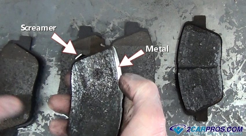
Chances are it is related to the brakes or the wheel bearing. First, inspect the pads, specifically on that side of the vehicle. Picture 1 shows what a worn pad looks like. Also, the component referred to as a screamer is a steel sensor that is designed to rub the rotor when the pad is worn. The purpose is to notify you that the pads need replaced before damage to the rotor occurs. If you find that the pads need replaced, here is a link that describes in general how they are replaced.
https://www.2carpros.com/articles/how-to-replace-front-brake-pads-and-rotors-fwd
___________________________
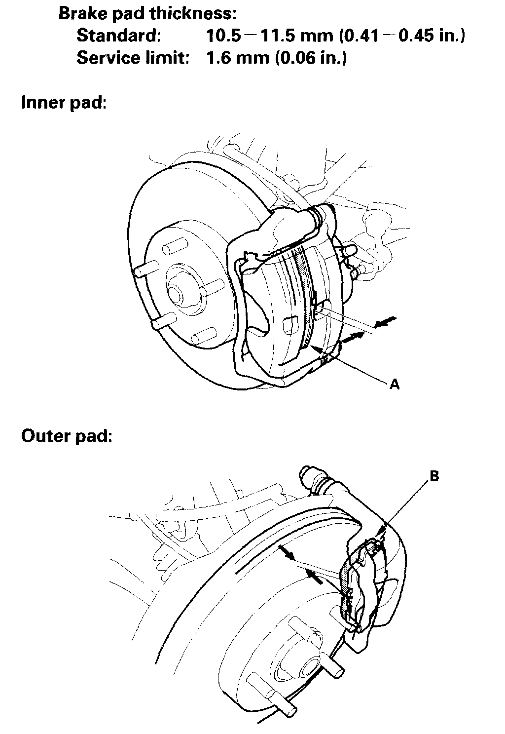
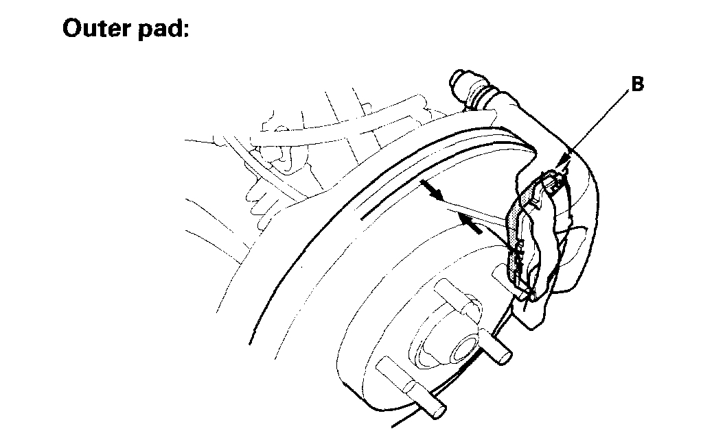
Here are the directions for brake pad inspection specific to your vehicle. Pictures 2 and 3 correlate with these directions.
Inspection
1. Raise the front of the vehicle, and make sure it is securely supported. Remove the front wheels.
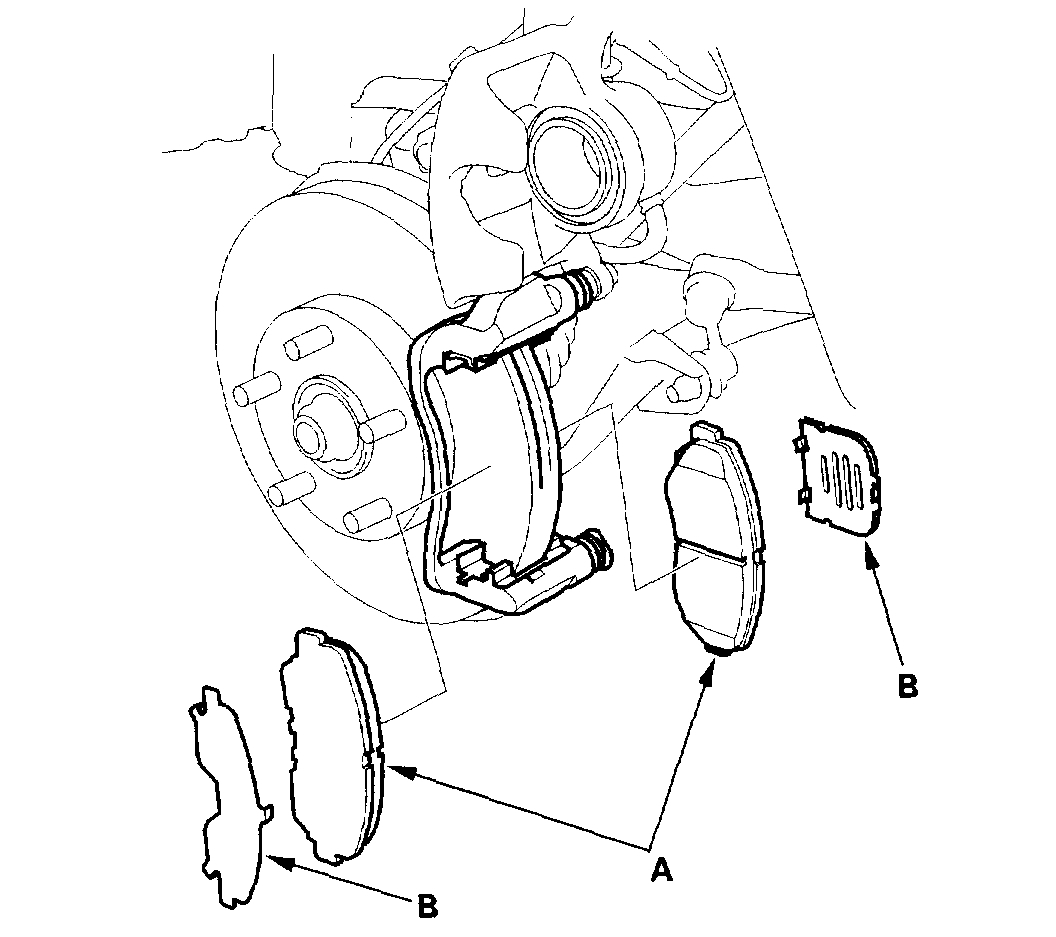
2. Check the thickness of the inner pad (A) and outer pad (B). Do not include the thickness of the brake pad backing plate.
3. If the brake pad thickness is less than the service limit, replace all the pads as a set.
_________________________
Here are the directions specific to your vehicle for front brake pad replacement. These directions are for a 4wd model. You didn't indicate which you had. If your vehicle is 2wd, let me know. The remaining pictures correlate with these directions.
________________________
Front
Vehicle Brakes and Traction Control Disc Brake System Brake Pad Service and Repair Procedures Front
FRONT
Front Brake Pads Inspection and Replacement
CAUTION: Frequent inhalation of brake pad dust, regardless of material composition, could be hazardous to your health.
- Avoid breathing dust particles.
- Never use an air hose or brush to clean brake assemblies. Use an OSHA-approved vacuum cleaner.
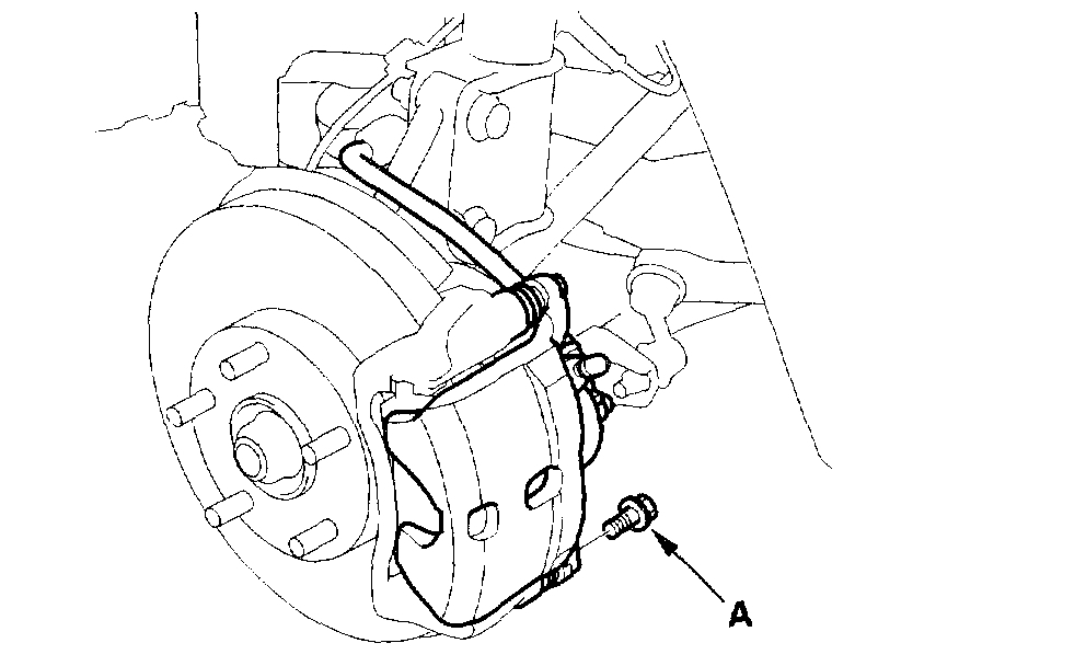
Replacement
1. Remove the flange bolt (A).
NOTE: The pad springs are installed on the pads to prevent brake drag. Be careful when pivoting up the caliper body fully, or the spring could be flipped out of the position.
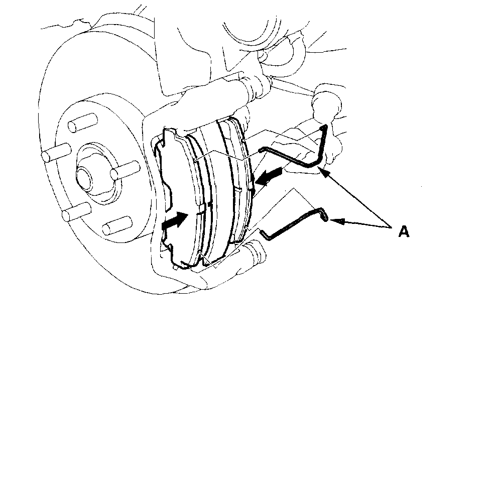
2. Pivot the caliper slightly so the pads do not come out of position, and hold the pads on both sides firmly with your fingers. Remove the pad springs (A) from the pads.
3. Pivot the caliper up out of the way, and remove the pads (A).
4. Remove the pad shims (B).
5. Check the hose and pin boots for damage and deterioration.
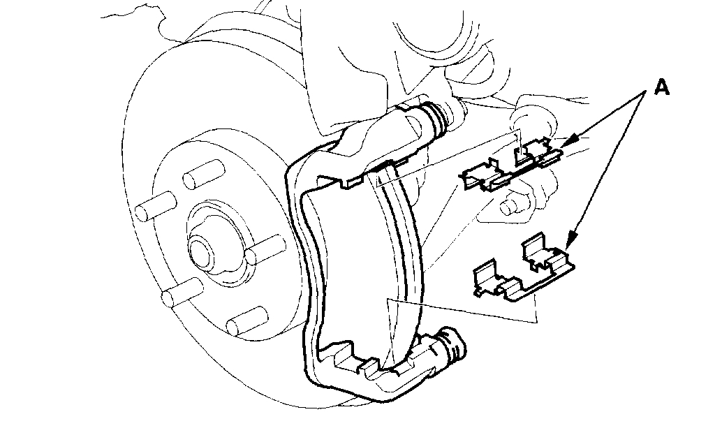
6. Remove the pad retainers (A).
7. Clean the caliper thoroughly; remove any rust, and check for grooves and cracks.
8. Check the brake disc for damage and cracks.
9. Install the pad retainers.
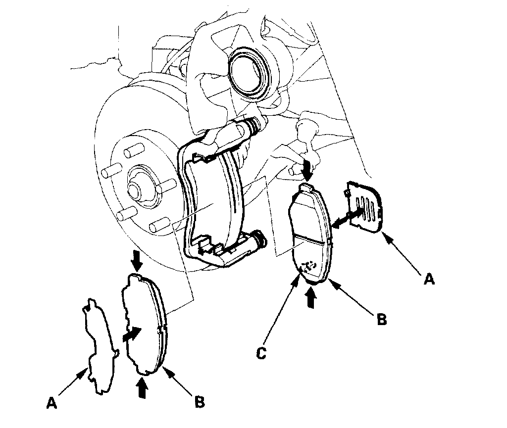
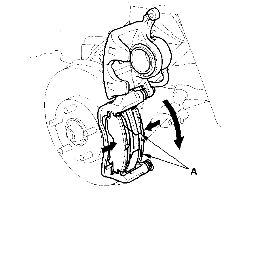
10. Apply Dow Corning Molykote M77 grease to both sides of the pad shim (A), the back of the pads (B), and the other areas indicated by the arrows. Wipe excess grease off the shim. Contaminated brake discs and pads reduce stopping ability. Keep grease off the discs and pads.
11. Install the brake pads and pad shims correctly. Install the pads with the wear indicators (C) on the inside. If you are reusing the pads, always reinstall the brake pads in their original positions to prevent a momentary loss of braking efficiency.
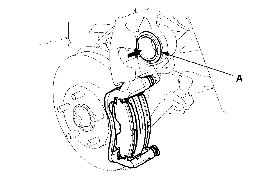
12. Push in the piston (A) so the caliper will fit over the pads. Check the brake fluid level. The brake fluid may overflow if the reservoir is too full. Make sure the piston boot is in position to prevent damaging it when pivoting the caliper down.
13. Hold the pads on both sides firmly with your fingers, and install the new pad springs (A) on the pads. Holding the pads, set the caliper over the pads by pivoting if down slowly.
NOTE: Insert the pad spring ends into the pad installation holes securely.
14. Pivot the caliper (A) down into position. Be careful not to damage the pin boots.
15. Install the flange bolt (B), and tighten it to the specified torque.
16. Press the brake pedal several times to make sure the brakes work, then test-drive.
NOTE: Engagement of the brake may require a greater pedal stroke immediately after the brake pads have been replaced as a set. Several applications of the brake pedal will restore the normal pedal stroke.
17. After installation, check for leaks at hose and line joints or connections, and retighten if necessary.
_____________________________
I hope this is helpful. As far as the wheel bearing, if the sound resembles a growing, changes with speed, and gets louder and softer based on turning, you may have a bad wheel bearing. If that is the case, here are the directions for replacing one. I will tell you, it requires a press to install the new bearing. It isn't a quick job. All remaining pictures correlate with these directions.
____________________________
FRONT / Bearing
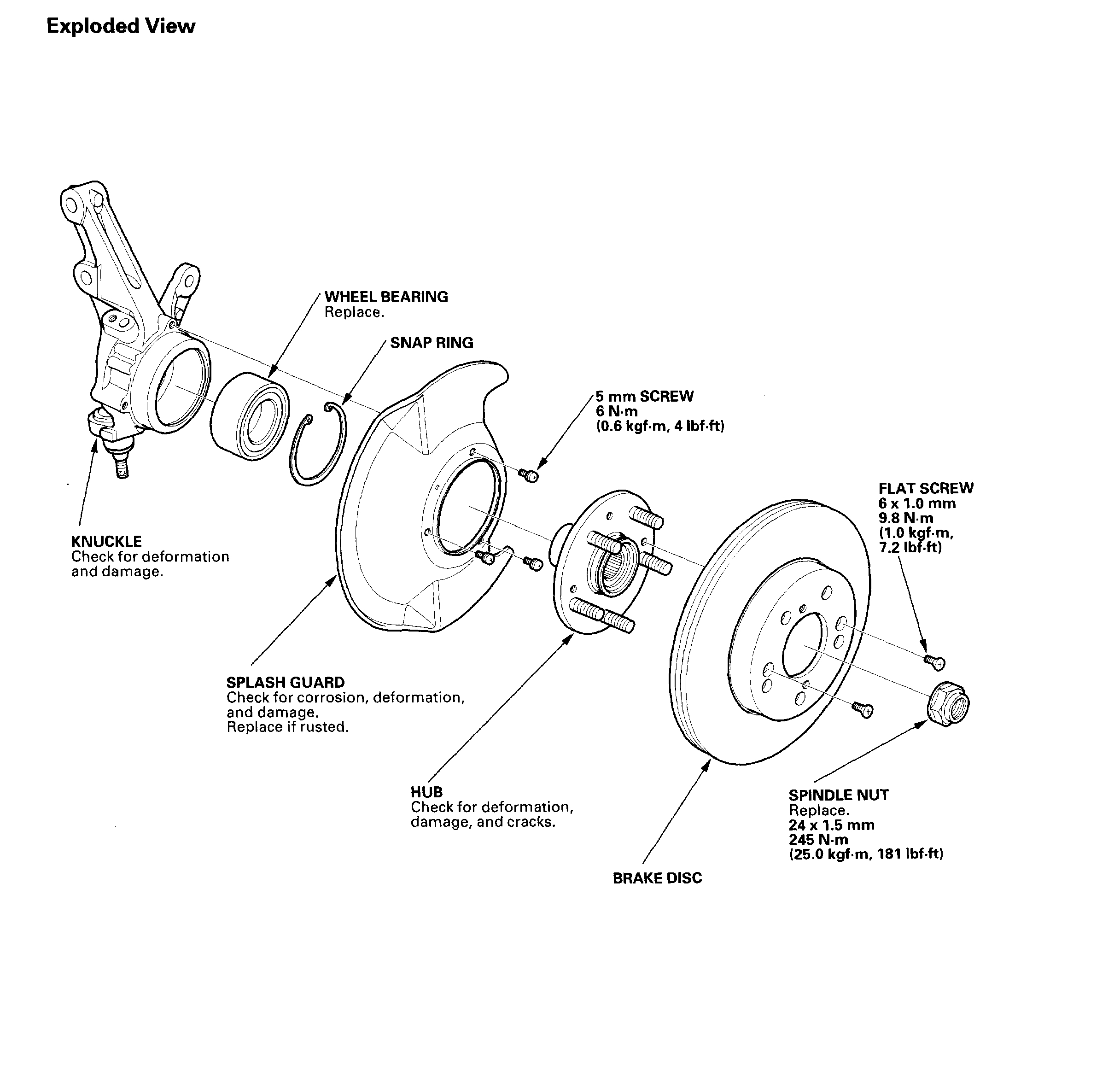
Knuckle/Hub/Wheel Bearing
Special Tools Required
- Hub disassembly tool 07GAF-SD40100
- Ball joint remover, 28 mm 07MAC-SL00200
- Attachment 62 x 68 mm 07746-0010500
- Driver 07749-0010000
- Support base 07965-SD90100
Knuckle and Hub Replacement
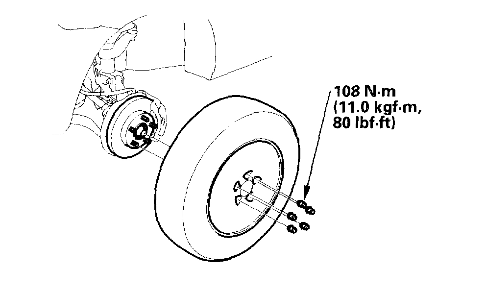
1. Raise the front of the vehicle, and make sure it is securely supported.
2. Remove the wheel cap, wheel nuts, and front wheel.
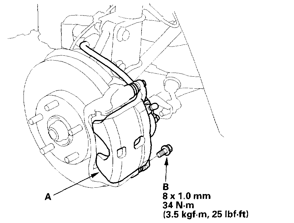
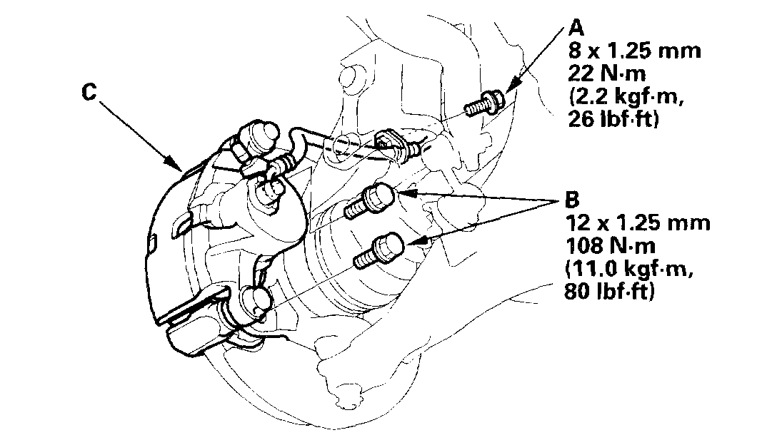
3. Remove the brake hose bracket mounting bolt (A).
4. Remove the caliper bracket mounting bolts (B), and remove the caliper assembly (C) from the knuckle. To prevent damage to the caliper assembly or brake hose, use a short piece of wire to hang the caliper assembly from the undercarriage. Do not twist the brake hose with force.
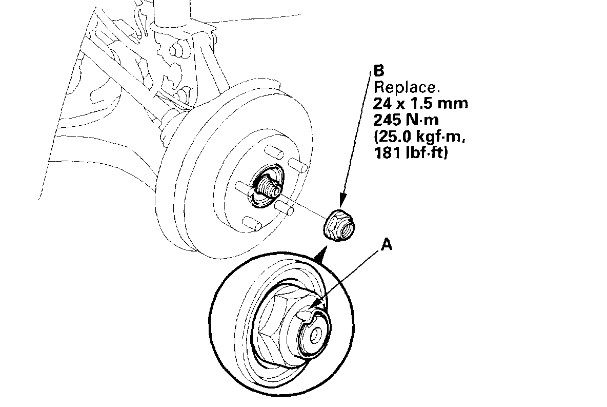
5. Raise the stake (A), and remove the spindle nut (B).
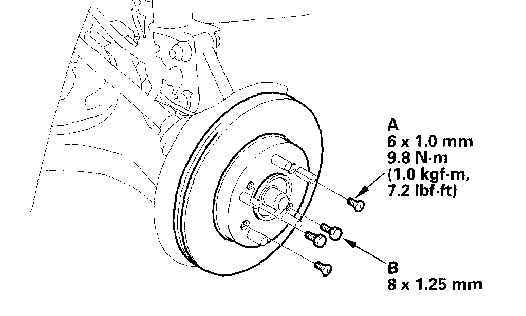
6. Remove the brake disc retaining flat screws (A).
7. Screw two 8 x 1.25 mm bolts (B) into the disc to push it away from the hub. Turn each bolt two turns at a time to prevent cocking the disc excessively.
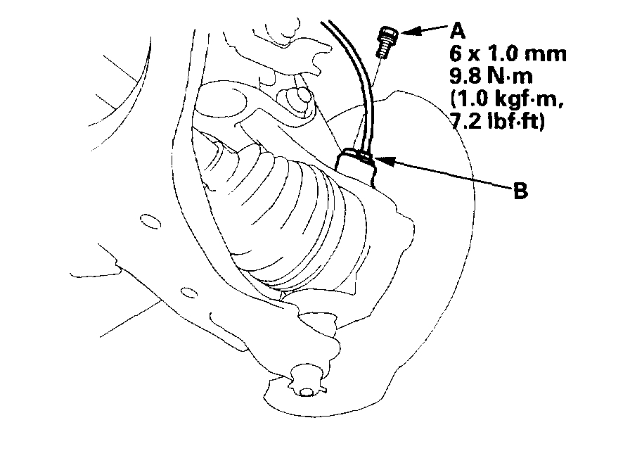
8. With ABS: Remove the flange bolt (A) and wheel sensor (B) from the knuckle. Do not disconnect the wheel sensor connector.
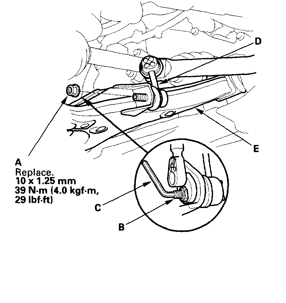
9. Remove the flange nut (A) while holding the joint pin (B) with a hex wrench (C), and disconnect the stabilizer link (D) from the lower arm (E).
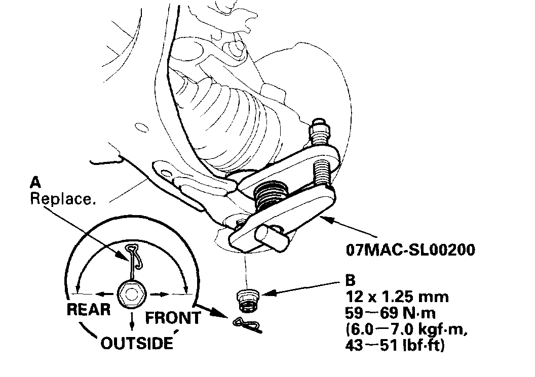
10. Remove the clip (A) from the lower arm ball joint, and remove the castle nut (B).
NOTE: During installation, insert the clip into the ball joint pin from the inside to the outside of the vehicle. The closed end of the clip must be in the range shown.
11. Disconnect the lower arm from the knuckle using the special tool.
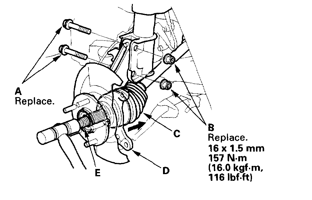
12. Loosen the damper pinch bolts (A) while holding the nuts (B), and remove the bolts and nuts.
13. Remove the driveshaft outboard joint (C) from the knuckle (D) by tapping the driveshaft end (E) with a plastic hammer while drawing the knuckle outward, then remove the knuckle.
NOTE: Do not pull the driveshaft end outward. The driveshaft joint may come off.
14. Install the knuckle/hub/hub bearing unit in the reverse order of removal, and note these items:
- Be careful not to damage the ball joint boot when installing the knuckle.
- Tighten all mounting hardware to the specified torque values.
- First install all the components and lightly tighten the bolts and nuts, then raise the suspension to load it with the vehicle's weight before fully tightening to the specific torques. Do not place the jack against the ball joint pin of the lower arm. Torque the castle nut to the lower torque specification, then tighten it only far enough to align the slot with the clip hole. Do not align the castle nut by loosening it.
- Install a new clip on the castle nut after torquing. Use a new spindle nut on reassembly. Before installing the spindle nut, apply a small amount of engine oil to the seating surface of the nut. After tightening, use a drift to stake the spindle nut shoulder against the driveshaft.
- Replace the self-locking nuts, damper pinch bolts and nuts with new ones. Before installing the brake disc, clean the mating surface of the front hub and the inside of the brake disc.
- Before installing the wheel, clean the mating surface of the brake disc and the inside of the wheel. Check the front wheel alignment, and adjust it if necessary.
Wheel Bearing Replacement
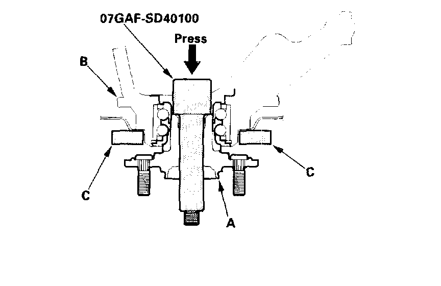
1. Separate the hub (A) from the knuckle (B) using the special tool and a hydraulic press. Hold the knuckle with the attachment (C) of the hydraulic press or equivalent tool. Be careful not to deform the splash guard. Hold onto the hub to keep it from falling when pressed clear.
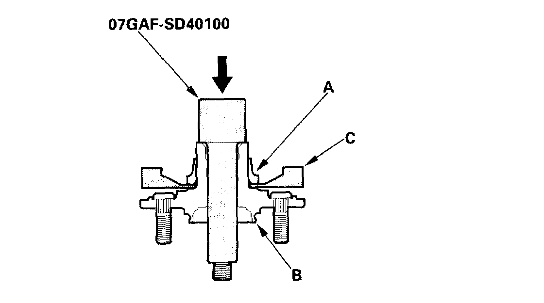
2. Press the wheel bearing inner race (A) off of the hub (B) using the special tool, a commercially available bearing separator (C), and a press.
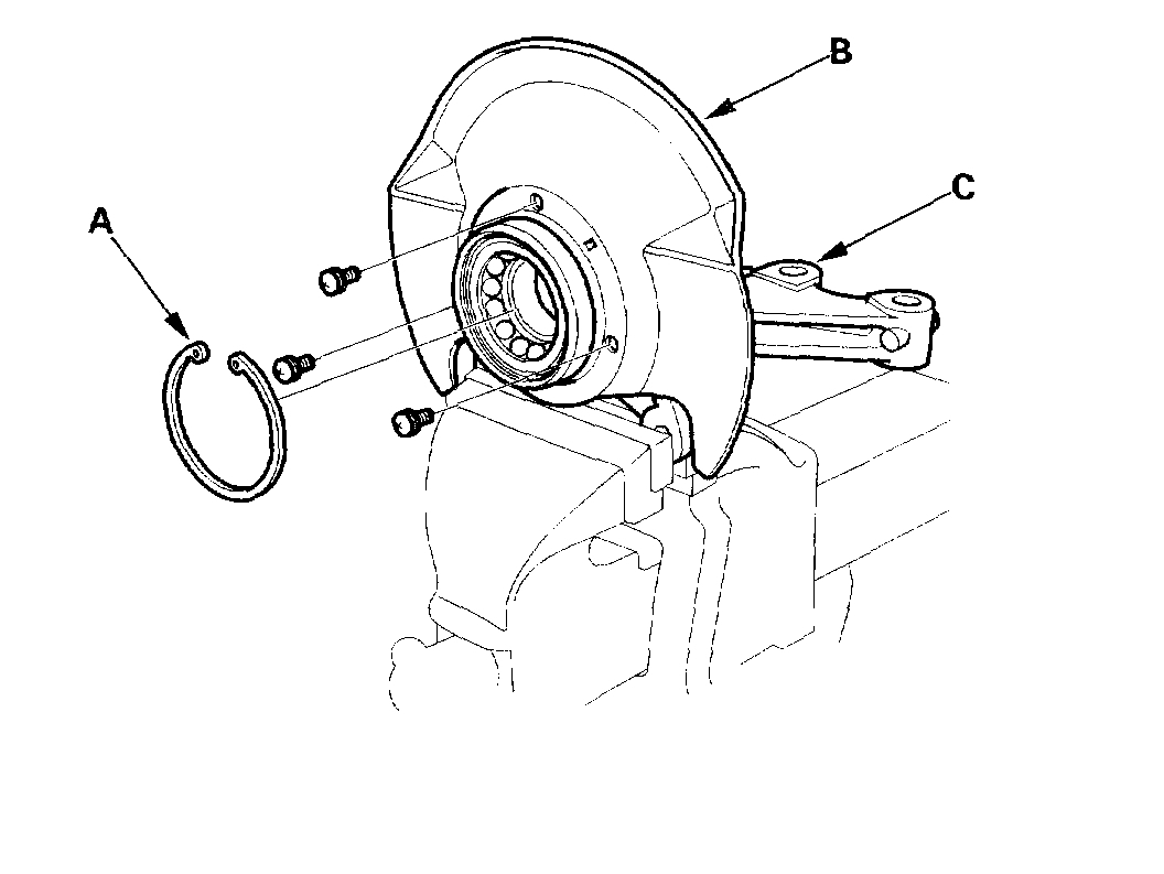
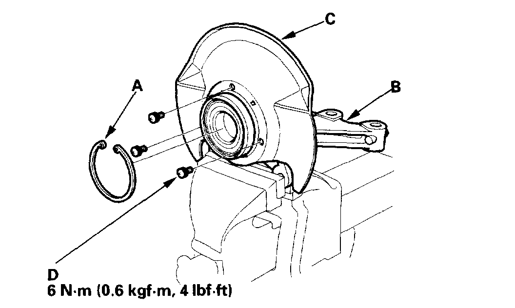
3. Remove the snap ring (A) and the splash guard (B) from the knuckle (C).
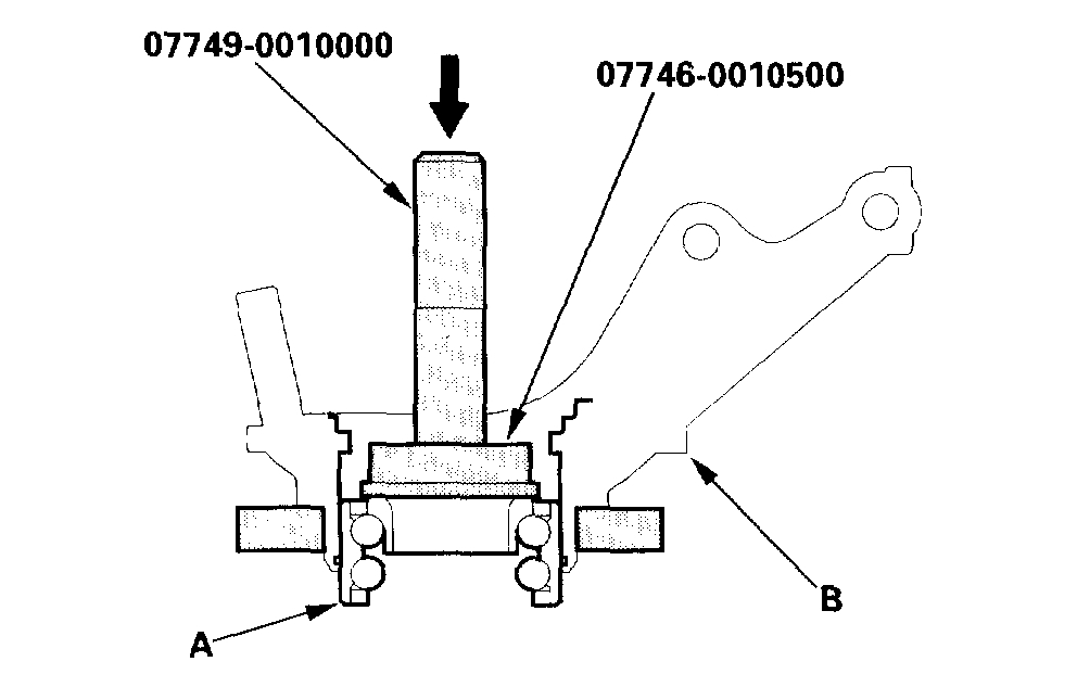
4. Press the wheel bearing (A) out of the knuckle (B) using the special tool and a press.
5. Wash the knuckle and hub thoroughly in high flash point solvent before reassembly.
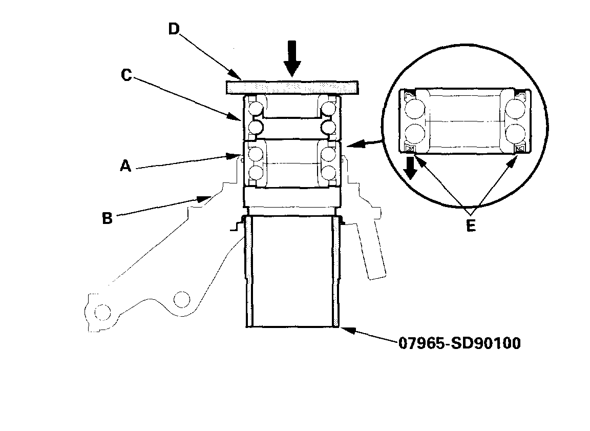
6. Press a new wheel bearing (A) into the knuckle (B) using the old bearing (C), a steel plate (D), the special tool, and a press.
NOTE (with ABS):
- Install the wheel bearing with the magnetic encoder (E) (brown color) toward the inside of the knuckle.
- Remove any oil, grease, dust, or other foreign material from the encoder surface.
- Keep magnetic tools away from the encoder surface.
- Be careful not to damage the encoder surface when you insert the wheel bearing.
7. Install the snap ring (A) securely in the knuckle (B).
8. Install the splash guard (C), and tighten the screws (D) to the specified torque.
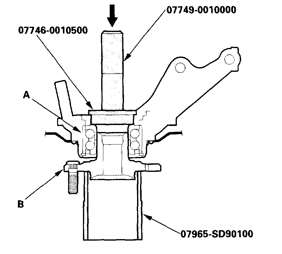
9. Press a wheel bearing (A) onto the hub (B) using the special tools and a press.
___________________________
If you have questions, please let me know. Also, let me know if this helps. If you are not comfortable working on a vehicle, I recommend getting help with either of these procedures. The wheel bearing is quite involved.
Take care,
Joe
Images (Click to enlarge)
Oct 16, 2018 at 7:36 PM