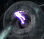
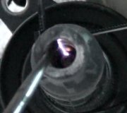
No spark from ignition coil

Tiny
TREV JT
  • MEMBER
  • 1991 FORD BRONCO
  • 5.8L
  • V8
  • 4WD
  • AUTOMATIC
  • 135,000 MILES
Hi, I am not getting spark at the engine coil. Turns over strong but will not start.

My ECT sensor and IAT sensor wire harness are testing out of range (.74V and not 5V). What could it be?


Additional information:
I am getting codes 21, 24, and 26.
Replaced ignition coil after old one tested out of range,
getting 40lbs consistent fuel pressure at rail.
brand new distributor and TFI/ICM after I broke mine trying to test the PIP
Just tested EEC - all tests okay.
Just tested with new battery. Same no start, still low voltage at the wire harness' of the two temperature sensors.
Tuesday, January 30th, 2018 AT 3:18 PM

8 Replies

Tiny
CARADIODOC
  • MECHANIC
  • 33,752 POSTS
Are you measuring the sensor voltages with them plugged in or unplugged? As usual, Ford does everything very differently than all other manufacturers. On your truck, you should find 5.0 volts feeding all the sensors, regardless if they are plugged in or unplugged. There are seven engine sensors that are fed from the same 5.0-volt source, and five of them should be setting fault codes if that 5.0 volts is missing. You only got two. Ford did have a really huge problem in the early 1990's with their coolant temperature sensors, but it is highly doubtful yours is still original. Other than that, temperature sensors have an extremely low failure rate because there is just one component inside them. More problems are caused by wiring and connector terminal problems.

It is rare to have a problem with one sensor circuit, so when you have three sensor related fault codes, plus a fourth symptom, the lack of spark, we should look at what all of these have in common. For starters, the ignition switch feeds the ignition coil and the "EEC" relay which powers up the engine computer. Turn the ignition switch to the "run" position, then check for twelve volts on the positive terminal on the ignition coil. If that is missing, the best suspect is the ignition switch.

If you have that twelve volts, next is to check if the EEC relay is turning on. The easiest way to do that is to check for twelve volts on the red wire at any injector. The best way is to poke the meter's test probe through the rubber weather seal in the connector, alongside the wire. If you have to, you can unplug an injector, then take the reading on the terminal. Be careful to not poke the probe into the terminal as that can spread it and result in an intermittent connection. A test light works just as well for these tests as does a digital voltmeter, however, given the nature of the measurements you have taken already, it might be better to know the exact voltages you find.
Was this
answer
helpful?
Yes
No
Tuesday, January 30th, 2018 AT 5:12 PM
Tiny
TREV JT
  • MEMBER
  • 7 POSTS
Hi! Thanks so much for the response! For the temperature sensors, I am measuring only the female end of the harness (unplugged) positive cable in the female hole and negative on the battery terminal (def should be getting 5 volts). I am getting three sensor codes (21, 24, 26: corresponding to air, coolant, and oil[and the no spark issue]). Also, my ECT looks pretty new. It makes sense that there is a wiring or connector terminal problem.

I just:
-Checked positive terminal of the ignition coil, getting full battery 12.3 volts
-Checked red wire at injector by piercing plugged in wire and getting full battery 12.3 volts
-This is the EEC Test I did this morning, everything checked out fine:

Maybe It is one of the other two wires that connect the ICM/TFI and the ignition coil?
Was this
answer
helpful?
Yes
No
Tuesday, January 30th, 2018 AT 7:08 PM
Tiny
CARADIODOC
  • MECHANIC
  • 33,752 POSTS
Be sure to seal the pierced wire with some silicone gasket sealer. I never allowed my students to cut wires to take readings. If you do that, be sure to seal them when you are done to keep moisture out.

Next, check for twelve volts on the red / light green at the TFI module's connector with the ignition switch in the "run" position. Then check for twelve volts on the red/light blue wire when the ignition switch is in the "crank" position. Check that the distributor shaft is rotating during cranking.

If this pans out, you will need a scanner to look at what the engine computer is seeing. It should show whether signal pulses are showing up from the pickup assembly in the distributor. You should also be able to run an actuator test that commands the computer to trigger the TFI module. If you get no spark, the suspects are the computer, the TFI module, and the wiring between them.
Was this
answer
helpful?
Yes
No
Wednesday, January 31st, 2018 AT 11:41 PM
Tiny
TREV JT
  • MEMBER
  • 7 POSTS
Thanks again for your help. I have got electrical tape over the pierced wire, will get that gasket sealer today.
Battery is at 12.01 volts
Red/light green at TFI module connector(unplugged) is getting 11.74 volts.
Red/light blue at when cranking is at 7.52 volts (unplugged).
The distributor is spinning during cranking.

Does this mean the connector is bad?
Was this
answer
helpful?
Yes
No
Thursday, February 1st, 2018 AT 10:41 AM
Tiny
TREV JT
  • MEMBER
  • 7 POSTS
Okay, so I found my Haynes manual and went through the chapter on Ignition problems. All checks are okay except for:

1. PRIMARY CIRCUIT CONTINUITY CHECK
"Check resistance between coil harness connector terminal TACH (coil negative) to ground. Measurement should be greater than 10,000 ohms. If the resistance is lower, repair the short in the harness and perform the general Ignition system checks"

I only measured 27 ohms

2. IGNITION CONTROL MODULE SUPPLY VOLTAGE CHECK
"Unplug wiring harness connector"
"attach negative lead of a voltmeter to distributor base"
"Turn ignition switch to Run position and measure the voltage at connector pin 2 and 3"
"Disconnect S wire on starter relay, turn ignition switch to start position and measure voltage at pin 3 again"
Turn ignition switch to start and measure for voltage this time at connector pin 4"

All tests gave over 90% of voltage EXCEPT for the final test at connector pin 4 it gave 7.4V

Haynes manual is telling me to
1. Repair the short in the harness
2. Service ICM power circuits to ignition switch for opens/shorts

Not sure what it means by this
Was this
answer
helpful?
Yes
No
Thursday, February 1st, 2018 AT 12:52 PM
Tiny
CARADIODOC
  • MECHANIC
  • 33,752 POSTS
12.2 volts means the battery is run down, and you have less than that. Charge it at a slow rate for at least an hour, so the rest of the tests can be trusted. A good, fully-charged battery will measure 12.6 volts.

Once you are done, get the electrical tape out of there too. That will unravel into a gooey mess on a hot day. The best way to prevent moisture from causing future problems from corrosion is to seal the wire with heat-shrink tubing with hot-melt glue inside. When that is not practical, the silicone sealant is the next best thing.

They had you unplug the red/blue wire at the starter relay so you could do testing in the circuit without cranking the engine, but it looks like that may have introduced a new clue. The twelve volts on that circuit feeds the starter relay and the TFI module. 7.4 volts there is not enough to make the starter relay engage, at least not nearly as strongly as normal.

The other problem is you are starting with a drained battery, and its voltage is going to be drawn down even more when cranking the engine to try to get it to start. If you only have 7.4 volts now, it will be less when the starter is working, and that is most likely the cause of the no-spark. Keep that wire unplugged from the starter relay, then measure the voltage on that wire when you turn the ignition switch to "crank". Also, remeasure at the red/blue wire at the TFI module. If you find anything less than full battery voltage while in the "crank" position, we'll have to work our way backward through the neutral safety switch, clutch interlock switch jumper wire, ignition switch, and all the associated wires and connector terminals to see where the voltage is dropping.

If the voltage is still low, as in near 7.4 volts, check it again after unplugging the TFI module. If that makes the voltage jump back up to around twelve volts, plug in the starter relay and listen if that sounds loud and healthy. I prefer to disconnect the large cable that goes to the starter motor so I can listen to the clunk of the relay without it being drowned out by the sound of the starter. You should hear a nice loud single clunk each time the ignition switch is turned to the "crank" position, but do not hold it there very long. The relay will overheat and start to smoke after about a minute, and that can cause the coil inside to warp and become permanently damaged. Do not ask me how I know that.

If you are not sure if the relay is nice and strong, measure the voltage on the red/blue wire at the unplugged TFI module. If you find close to twelve volts, but it drops to 7.4 volts when plugged in, that module is likely shorted and is drawing the voltage down.
Was this
answer
helpful?
Yes
No
Saturday, February 3rd, 2018 AT 2:00 PM
Tiny
TREV JT
  • MEMBER
  • 7 POSTS
Ok so I got the battery charged but it drains way faster then it should be so I’m going to need a new one. Also I got the electrical tape out.

The car started today! It was a combination of cleaning the starter relay wires and unplugging the spout connector that got me my spark. The car dies with the SPOUT in so I still have some sort of short going on. Will go through the rest of your tests to figure out the underlying issue.

Thanks again for your help. Big time.
Was this
answer
helpful?
Yes
No
Sunday, February 4th, 2018 AT 10:40 PM
Tiny
CARADIODOC
  • MECHANIC
  • 33,752 POSTS
Don't have an answer for that. On older Fords, the starter solenoid on the inner fender had a second small terminal that switched on during cranking to bypass the ignition system's ballast resistor. That resistor lowers average voltage to protect the ignition coil. Add to that the lower battery voltage that is drawn down by the starter, and the voltage at the ignition coil can be too low to produce a nice strong spark. That resistor is bypassed during cranking to return spark voltage to normal levels for easier starting.

Ford had at least three variations of this starter system. One of them used that second small terminal for the neutral safety switch. As such, they had to bypass the resistor a different way.

Your truck is shown with a still different circuit. 12 volts if fed directly to the ignition coil all the time. Nothing in the ignition system is switched by the starter relay.
Was this
answer
helpful?
Yes
No
Monday, February 5th, 2018 AT 4:20 PM

Please login or register to post a reply.

Sponsored links