Rats. The closest I have is a '71 book, but it doesn't have this system. I do have the information that I used in the classroom. Unfortunately that is on a record and filmstrip, so I'll have to do this from memory.
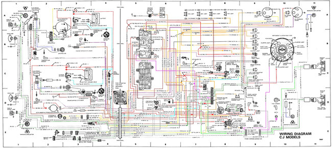
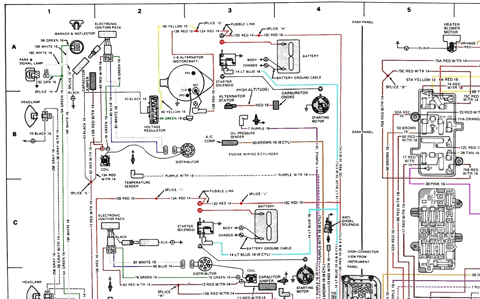
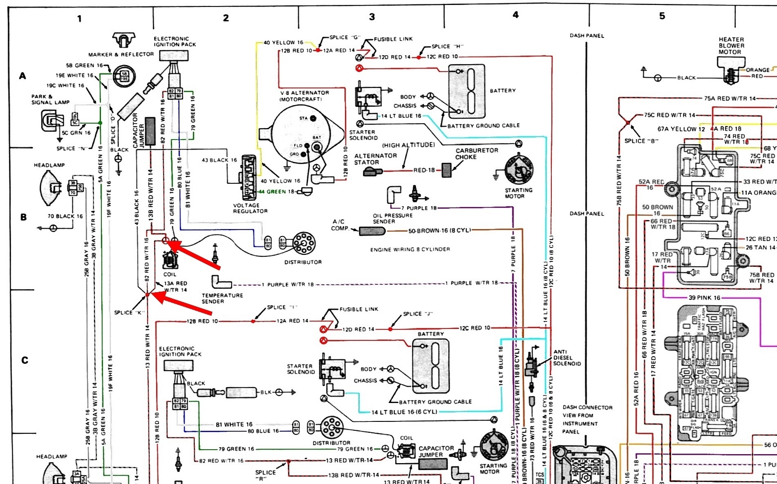
I did find the wiring diagram online but it doesn't reproduce very well. The entire vehicle is shown in the first diagram. I expanded the ignition system section in the second diagram below to work from. This ignition system was first used in 1970, and many people think it was the first electronic ignition system. While it does use an electronic control module, it is triggered by breaker points in the distributor. The problem with breaker points, at least as far as the politicians were concerned, is the instant a new set was put into service, the rubbing block started to wear down. That affects when the points open, that affects ignition timing, and that affects emissions. Never mind the ignition timing could still be adjusted all over the place.
Chrysler actually had the first truly electronic ignition system in 1972 on Dodges, and 1973 on Chryslers and Plymouths. GM came out with their High Energy, (HEI) system on '76 models. Ford and AMC are in there somewhere too. I seem to recall Ford's first electronic system showed up in 1977, but that could be wrong.
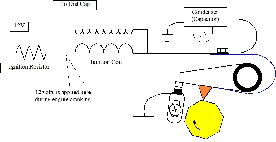
The basic breaker point ignition system is shown in the third diagram. The resistor you asked about is on the left. Without that resistor, when the points are closed, (switched on), current flow would be limited only by the small resistance of the ignition coil's primary half. While that high current is good for building up a strong electromagnetic field in the primary coil, it's way more than necessary. The down side is that current causes a lot of arcing across the contact points when they open, (switch off). The condenser reduces that arcing, but it won't totally eliminate it. Because of the pitting it causes, the breaker points typically have to be replaced about every 10,000 miles.
Another problem occurs during cranking. To help visualize what happens, imagine that two of the 12 volts gets "dropped" across the resistor. That leaves the remaining ten volts across the coil. At ten volts, the electromagnetic field is strong enough to produce sufficient spark plug voltage. 12-volt electrical systems actually run between 13.75 to 14.75 volts when the engine is running. All systems including the ignition system are designed around that voltage. When the engine is not running, a good, fully-charged battery will be close to 12.6 volts. Where the problem pops up is due to the extremely high current the starter motor draws, it pulls the battery voltage down a lot, possibly as low as less than ten volts. Now, starting with only ten volts, and dropping some of that across the ballast resistor, we're left with perhaps as little as 8 volts across the ignition coil. There will still be voltage developed in the coil's secondary, but it will be very low, possibly not high enough to create a spark across all of the spark plugs, or that spark will be very weak.
To address that weak spark, the ballast resistor gets bypassed during cranking. That puts full battery voltage, which now is around ten volts, across the ignition coil, so it is back to developing normal spark voltage. That's kind of hard on the breaker points, but this only occurs during cranking. The main benefit is easier and faster starting. Chrysler switches the 12 volts on with an extra, dedicated terminal on the ignition switch. GM does this through a second, dedicated terminal on the starter solenoid. It has an "R" molded next to that terminal for "relay". Ford also did this through their starter solenoid, but it is up on the inner fender, near the battery. Be aware there are at least three different versions of the Ford-style solenoid, and they are not interchangeable. One of those is used on AMC models.
The important point of this story is all the current that flows through the ignition coil is switched on and off by the breaker point's contacts. That's a lot to ask of them.
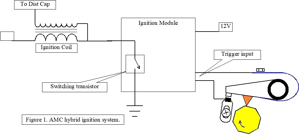
Your ignition system is the first step in solving the shortcomings. It's shown in the fourth diagram. Here, the ignition coil's primary current flow is switched on and off by a large power transistor inside the ignition module. The module does that when it gets a signal pulse, or "trigger" from the breaker points. Those points are adjusted the same as before. The only thing that has changed is there's no arcing across them when they switch off. That eliminates the worst maintenance issue. The only thing that hasn't been addressed is the wear on the rubbing block, (orange triangle).
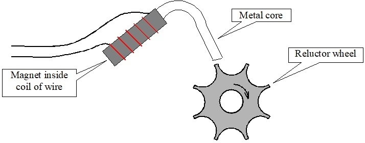
The next step in the evolution of this system is the Chrysler system from 1972. An ignition module is used just like in the AMC system, but the breaker points are replaced by a two-wire magnetic pickup coil, shown in the fifth drawing. The only moving part is the "reluctor wheel" on the shaft of the distributor. There's one more thing, but you can't see it. Just like in any ignition coil and in every generator, three things are needed to generate a voltage, (electrical pressure), mechanically. Those are a wire, a magnetic field, and most importantly, movement between them. A coil of wire is much more efficient than a single wire. The magnetic field can come from an electromagnet such as in a generator or ignition coil, or it can come from a permanent magnet as used in this distributor pickup coil. That magnet sets up a magnetic field around the tip of the metal core. The movement comes from disturbing that field when a tooth of the reluctor wheel passes by it. That invisible movement is what induces a small pulse of voltage in the coil of wire, and that voltage pulse is what triggers the module to switch the power transistor off. That interrupts current flow through the primary side of the ignition coil, then the collapsing magnetic field in there induces the huge voltage in the secondary coil. Here too, the movement is the collapsing magnetic field.
Up to this point, all distributors have one thing in common. They all adjust spark timing based on engine speed and load. When ignited, the fuel does not explode instantly. It takes some time to burn. At higher engine speeds, to get the most power from that burn, it has to begin sooner so it finishes at the right time. The distributor's shaft is a two-part shaft with the lobed cam wheel sitting on the top part. That's the 4, 6, or 8-sided cam, (yellow octagon in the fourth diagram), That part rotates ahead thanks to a pair of spring-loaded fly weights. As it rotates, the lobes show up sooner and open the breaker points sooner. That advances spark timing.
The plate the breaker points or pickup coil sits on can also rotate. In the most common design, it gets pulled on by a vacuum assembly connected to a vacuum port just above the throttle blade in the carburetor. As the throttle blade opens past that port, vacuum is applied to that vacuum assembly to move the breaker points causing them to open sooner. That is done to improve fuel mileage. With a high load on the engine, intake manifold vacuum drops. Vacuum to the distributor drops, then that part of the spark timing advance goes away to prevent preignition, or spark knock.
The final evolutionary step in distributor design did away with both of the timing advance systems. Only a stationary magnetic pickup coil was used, never breaker points. Timing advance was handled by a computer. The first attempt at this was Chrysler's "Lean Burn" computerized ignition system in 1976. It used a number of sensors to calculate optimum spark timing. The problem is you can't get a trigger pulse from the pickup coil, and then the computer wants to fire the ignition coil some degrees before that pulse occurred. By that time it's too late. Instead, all computer systems start out with a greatly advanced base timing, then the computer calculates how long to wait before firing the ignition coil. For example, it would typically begin with the pickup coil developing a signal pulse at 40 degrees before top dead center. The computer might calculate a timing delay of 30 degrees. After waiting that long, then firing the ignition coil, you end up with spark at 10 degrees before top dead center.
Today spark timing is adjusted the same way with a computer and sensors, but they are mounted on the engine. Reluctor wheels are on the crankshaft and on the camshaft.. These are much more precise because any wear or wobbling between the distributor shaft and its bushings are eliminated, along with small fluctuations caused by worn and sloppy timing chains.
Some of the earliest computerized ignition systems still used a ballast resistor. They cut down on current flow through the ignition coil and reduce the stress on the delicate switching transistors.
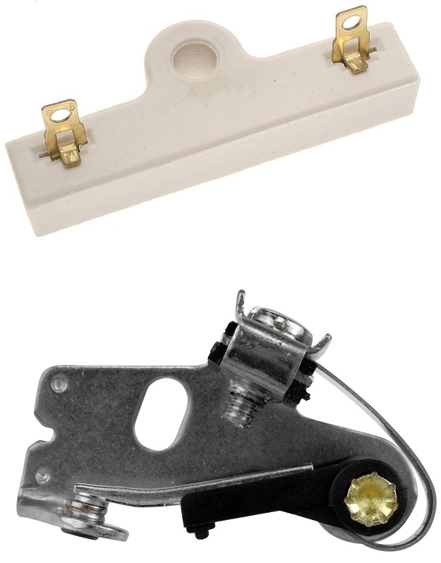
Now that I've shared all of this wondrous information, we should check if you actually have this ignition module on your Jeep. The expanded view of your system in the second diagram shows the ignition module, but no reference is made to a ballast resistor. In looking up the parts, I did find the resistor, but no module listed. That suggests there may have been two different ignition systems used during the model year. The resistor is of the standard, or common design. It is at the top of the sixth photo, along with the breaker points below it.
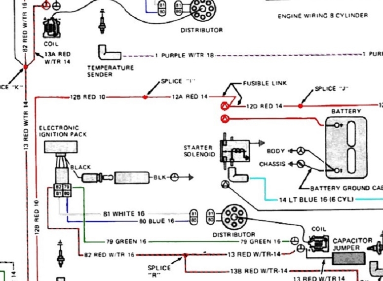
If there is supposed to be a resistor used with the ignition module system, you would have to cut the red wire between the two red arrows I added in the seventh diagram, then connect the two ends to the two terminals on that resistor. It can't go in any other part of that wire as it feeds other things that won't work properly if that resistor is in there. That's for the 8-cylinder engines. The 6-cylinder system is just below it and partially cut off, but it's the same diagram. Again, no resistor is shown, so if one is needed, it could very likely be built into the ignition module.
Images (Click to enlarge)
Mar 27, 2023 at 4:19 PM