No electrical power?

Tiny
VFONTAN
  • MEMBER
  • 2007 GMC SIERRA
  • 5.7L
  • V8
  • 4WD
  • AUTOMATIC
  • 207,000 MILES
The vehicle listed above is a Classic SLE model.

I drove the truck yesterday morning and after stopping at a gas station the truck made a clicking noise as if the battery was weak (only 3 or 4 cast clicks), but the starter engaged right away, and it cranked and it started normal (not a lazy start).

After I parked for about two hours at home, I tried to start it, I heard the clicking sound (I assume the starter trying to engage) and then nothing, no power to anything. I noticed the gage needles did not drop all the way down (ex. Fuel stopped a 1/4 tank, temp stopped at around 100, volts stopped at around 6v, etc.)

The battery read zero volts on the meter, so I connected a solar battery tender. When I connected the tender I had power on the dash (the gages re-set), the door chime, and enough power to at least roll up the windows. This morning the battery reads 12.86V but I still have no power to anything.

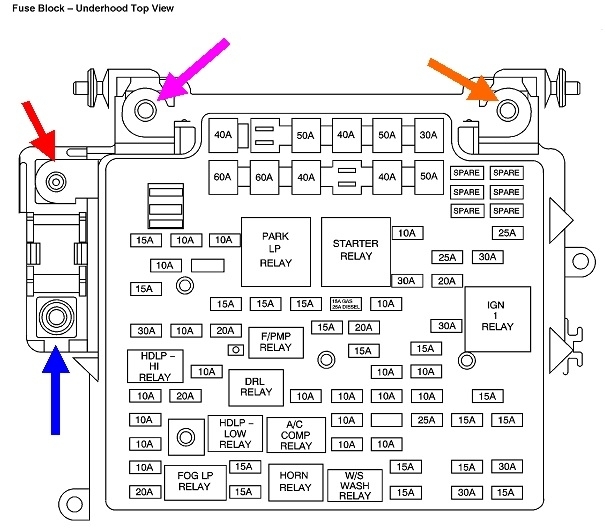
I verified I had good ground between the battery, fuse block, and body, I tried to identify a parasitic draw, removed and checked all the fuses, and verified all wiring to the fuse block was good, all to no avail.

After several hours of frustration and being unable to identify any fault, I reassembled everything and just like that, the truck started fine, and I was puzzled.
I connected a code reader and got the following codes:
-P0030 HO2S Heater Control Bank 1 Sensor 1
-HO2S Heater Resistance Bank 1 Sensor 1
-P0134 (02 Sensor Bank 1)
-P0480 (Fan 1 Control Circuit)

I erased the codes and read them again and only
-P0134 (02 Sensor Bank 1)
-P0480 (Fan 1 Control Circuit)
returned but those 2 codes are not new.

I am at a loss here, I learned nothing, and I am back to square 1. What could have caused the sudden loss of electrical power and possible battery drain?
Tuesday, May 2nd, 2023 AT 11:41 AM

3 Replies

Tiny
CARADIODOC
  • MECHANIC
  • 33,752 POSTS
To get you started, this is a very common symptom on all car brands. Look at the smaller battery positive wire and follow that to the under-hood fuse box. Clean or tighten that connection. If you wait until the problem occurs again, and then tighten that connection, you'll know right away if that restores power. An alternative is to do a "voltage drop" test, but that has to be done while the problem is occurring. I can walk you through that. All you need is a digital voltmeter, which it sounds like you have and know how to use.

Next, follow the smaller battery negative wire to the body sheet metal. Be sure that connection is tight and not rusty.

It looks like there's up to four nuts to check. All I have to go by is this drawing. I can't find any model listed with a 5.7L engine. This is for a 5.3L. They show two batteries. Am I seeing that right?

Let me know what you find.
Was this
answer
helpful?
Yes
No
Tuesday, May 2nd, 2023 AT 12:35 PM
Tiny
VFONTAN
  • MEMBER
  • 2 POSTS
It is a 5.3L, my bad! I am thinking it was the small positive cable going to the fuse block. I disconnected it to be able to raise the fuse block and check the wires under it. Even though the connection was tight and looked free of corrosion, disconnecting it and reconnecting may have done it. So far so good. If it happens again, I'll go directly to that positive cable first. Is adding dielectric grease recommended to help prevent corrosion?
Was this
answer
helpful?
Yes
No
Tuesday, May 2nd, 2023 AT 3:42 PM
Tiny
CARADIODOC
  • MECHANIC
  • 33,752 POSTS
No. It will take ten vehicle lifetimes for those huge terminals to corrode away. What happens is there's a lot of current flowing through those connections at times. Just the slightest amount of corrosion or less-than-perfect connection creates resistance, and that translates into heat. That heat degrades the connection creating more resistance and heat until arcing occurs. As that progresses, the area of good contact gets smaller and smaller. As it does, all of the current has a smaller area to pass through so things just keep getting worse. The final straw is when there is so little area of contact, that last little bit burns away the next time you try to start the engine. Usually just tightening the nut restores power and gets you home where you can take the cable apart and clean and tighten it properly.

In your case, it looks like there can up to four nuts to tighten. I can't tell from the drawing, but a lot of manufacturers are doing that now where there's multiple fuses at those large connections.

If you hit the right connection, even if this doesn't solve it, the symptoms are likely to act differently. In case this acts up again, I can go into more detail, but for now, it's the voltage drop test that can prove where the bad connection is. We're only interested in mechanical connections for now. That means a place where two parts are bolted together. The battery wire to the fuse box terminal is one. The two big ones that used to cause this problem are where the positive cable clamp is bolted to the positive battery post, and where the negative cable clamp is bolted to the negative battery post. We don't count where a battery cable clamp is molded to the cable. The exception would be if a cable clamp was cut off, then a universal clamp was attached with a strap and two bolts. Now we have another mechanical connection. Those universal clamps are never intended to make a permanent repair. They're designed to get you back on the road until you can get a new cable. Those can work well, so a lot of people think they are a permanent repair.

For this test to work, you have to turn on at least one high-current circuit, even when nothing is working. The purpose is we need to have current trying to flow, otherwise no voltage drop will ever show up. The most common high-current circuit is the headlights. If you don't have a computer-controlled heating system, you can use the heater fan instead. When the defect is occurring, whatever you have turned on will not be working. The goal now is to keep it that way. Don't wiggle and fiddle with anything in an attempt to get it to work.

The voltage drop test is done by measuring the voltage on the two parts of each mechanical connection. It doesn't matter where you start, but I like to start at the battery. Place one meter probe on the positive cable clamp, and the other probe on the positive battery post. (The two probes will be about 1/4" apart). Those are the same place in the circuit, so the voltage should be the same at both points. The voltmeter should show 0.00 volts. If that mechanical connection is less than perfect, you'll find some voltage drop there, but again, only when current is trying to flow through it.

Now do that same test at the negative post and cable clamp. If they both show very close to 0.00 volts, move on to the better suspects. That's those wires bolted to the fuse box. This gets a little trickier. One meter probe must go on the terminal on the end of that wire, not on the nut. The other probe must go to the stud that nut is on. If you find anything substantial, that is the connection that must be cleaned. You're supposed to find 0.00 volts there. Do the same test for any other fat wires bolted to that fuse box. To be fair, you can expect to see a little voltage drop, say in the order of a few hundredths of a volt. Normally when a connection is bad enough to cause something to be dead, you're going to find well over four volts, and maybe even the whole 12 volts.

The last mechanical connection is where the smaller negative battery cable is bolted to the body sheet metal. I had this one break due to rust on the coldest winter day in Wisconsin a few years ago.

This is the same test we do in starter circuits, although those bad connections are usually easier to find. An older Ford or GM starter wants to draw up to 300 amps until it gets up to speed. Once spinning, that drops down to around 200 amps. With current that high, it takes far less resistance than we can measure to stop the circuit from working. A misguided continuity test will falsely show everything is okay. While we can't measure resistance that small, we can measure the RESULTS of that resistance. That is this voltage drop test. The industry standard is we're allowed up to a maximum of 0.2 volts per mechanical connection, and no more than 0.4 volts for the entire half of that circuit. The other half is the negative battery cable where it bolts to the engine. You have one mechanical connection between the battery post and the negative cable clamp, and a second one between the other end of that cable and the engine.

With older Fords, the positive half of the starter system was full of mechanical connections. Besides the one at the battery positive post and the one at the starter, that cable is in two pieces, each with an end on the starter solenoid. There's also two mechanical contacts inside the starter solenoid. Every one of those connections can have no more than 0.2 volts drop, and all six of them together can have no more than 0.4 volts drop in total. You have those two internal solenoid contacts too, but we can't get to them with the meter probe, so we don't count those in this test.

The drawing below is of a "Notes Page" I handed out in class. This is for starter circuits, but the idea is the same with fuse boxes.

Now that I shared all that wondrous information, a number of people will tell you they found the bad connection at the fuse box by the sparks they saw when tugging on one of the wires. That is also proof that connection is in poor condition, but this too will only show up when a high-current circuit is turned on.

Let me know if you have this solved already, or how this voltage drop test works if you need to do it. You can do this test too when everything is working to get an idea of what "normal" is for each connection.
Was this
answer
helpful?
Yes
No
Tuesday, May 2nd, 2023 AT 9:18 PM

Please login or register to post a reply.

Sponsored links