Hi,
It is likely the sensor, but here is how you check. You will need a general multimeter to perform this.
1) First, you need to check for power at the connector which is attached to the sensor. If you look at pic 1, it shows the connector. Pin A is the ground and pin B is the power supply. First, check to see if there is power to pin B. It should be around 5 volts.
2) If there is power, you need to check for continuity to ground. Set the multimeter to ohms and probe pin A with one of the red prong on the meter and ground the other to check for continuity.
3) If that checks good, next check the sensor for resistance. Again, with the multimeter on the ohms setting, touch each pin on the sensor You should be around 1.5 to 2.0 ohms of resistance at ambient temp. If it shows 0, replace the sensor.
_________________________________
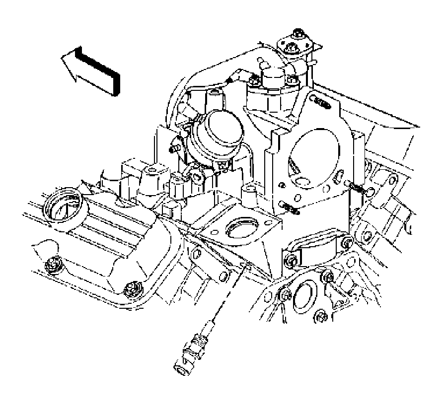
Here are the directions for replacing the sensor. Pics 2 and 3 correlate with the directions.
2005 Chevrolet Impala V6-3.8L SC VIN 1
Procedures
Vehicle Powertrain Management Sensors and Switches - Powertrain Management Sensors and Switches - Computers and Control Systems Coolant Temperature Sensor/Switch (For Computer) Service and Repair Procedures
PROCEDURES
ENGINE COOLANT TEMPERATURE (ECT) SENSOR REPLACEMENT
REMOVAL PROCEDURE
NOTE: Use care when handling the coolant sensor. Damage to the coolant sensor will affect the operation of the fuel control system.
1. Partially drain the cooling system. Refer to Draining and Filling Cooling System in Cooling System.
2. Remove the thermostat housing.
3. Disconnect the ECT sensor electrical connector.
Pic 2
4. Remove the ECT sensor.
INSTALLATION PROCEDURE
NOTE: Use care when handling the coolant sensor. Damage to the coolant sensor will affect the operation of the fuel control system.
Pic 3
1. Coat the threads with sealer GM P/N 12346004 (Canadian P/N 10953480) or equivalent.
NOTE: Replacement components must be the correct part number for the application. Components requiring the use of the thread locking compound, lubricants, corrosion inhibitors, or sealants are identified in the service procedure. Some replacement components may come with these coatings already applied. Do not use these coatings on components unless specified. These coatings can affect the final torque, which may affect the operation of the component. Use the correct torque specification when installing components in order to avoid damage.
2. Install the ECT sensor.
NOTE: Refer to Fastener Notice in Service Precautions.
Tighten the ECT sensor to 20 N.M (15 lb ft).
3. Connect the ECT sensor electrical connector.
4. Install the thermostat housing.
5. Fill the cooling system. Refer to Draining and Filling Cooling System in Cooling System.
_________________
Let me know if this helps or if you have other questions.
Take care,
Joe
Images (Click to make bigger)
Tuesday, November 17th, 2020 AT 9:14 PM