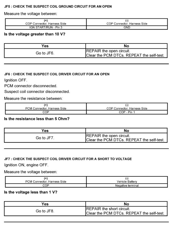
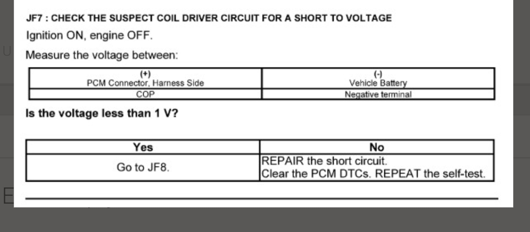
So the wording of this test is confusing, I can understand that, what we're trying to figure out is if there is power on the control circuit with the coil unplugged, technically speaking this circuit should not have a path to ground without the PCM's coil #4 transistor energized. Following this flow chart it appears they want you to check for voltage at the PCM connector (harness side) with it disconnected, and key On. Its possible for the circuit to be shorted to a "Hot at all times" wire, in which you would read battery voltage (12v) with the key Off. What they are looking for is a key On short to voltage, which could be either 12v or 5v. They should word these things better, hence the reason I dont like flow charts but they do provide some helpful diagnostic steps. So with the coil and PCM unplugged we should be isolating the circuit from everything else.
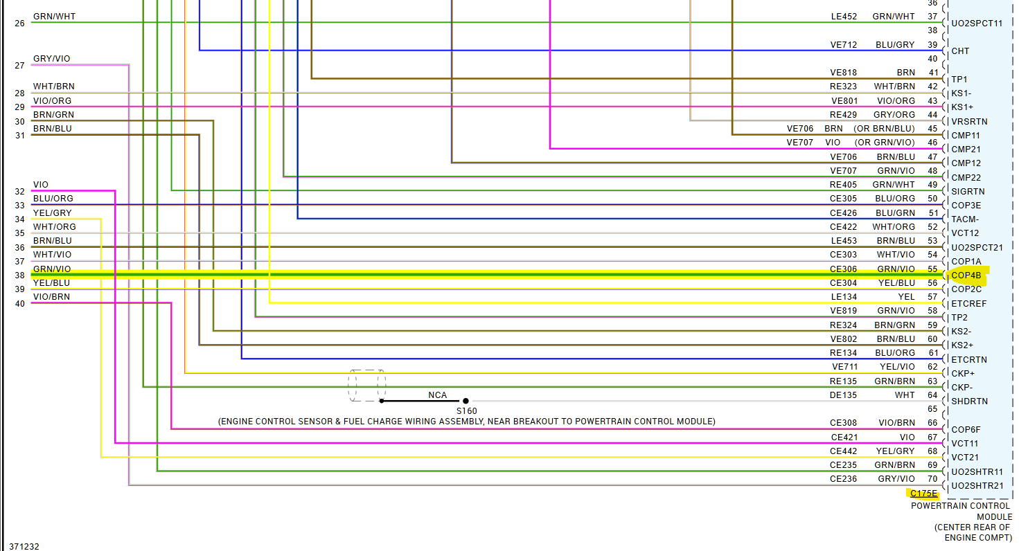
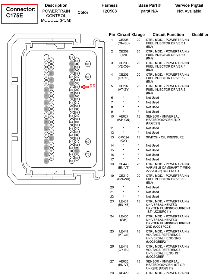
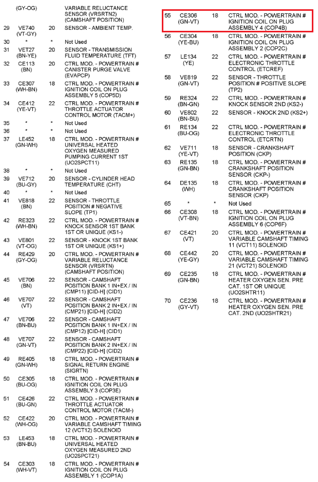
Looking at the PCM connector pinout diagrams all I see on connector C175E are mostly all sensor signals (inputs) and control driver circuits, having this connector unplugged with the key On may or may not set a bunch of codes, Im sure it will set some circuit fault codes. So after testing, turn the key Off and hook up a scan tool to clear all the codes, then go key off again for a few seconds to make sure they all clear.
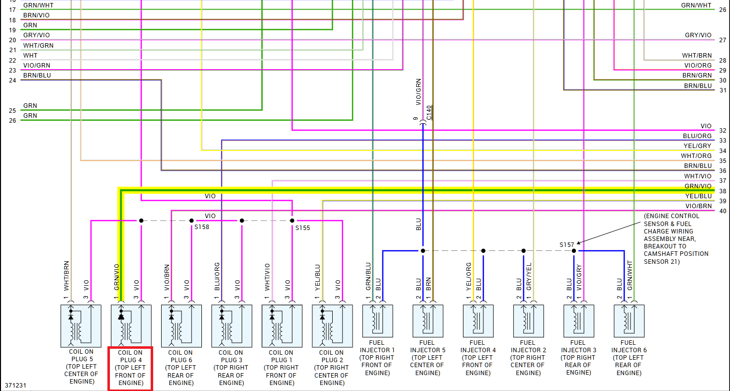
If the coil is still plugged in, and key On, at the disconnected PCM connector you will read 12volts. Because youre reading the power coming through the coil to the PCM connector and your other lead is on battery negative. So you want the coil unplugged.
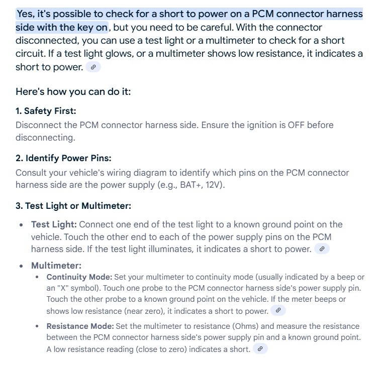
Instead of a multimeter I would use a very low current test light for the first check, many places sell LED test lights for automotive testing now so its safer for PCM circuits, since we dont know what the possible short to power's source is yet. With the PCM disconnected and key On, the other wires for the PCM connecters will be hot and still plugged in, so we want to be as careful as possible with this test.
If its not a bad PCM, we dont want to make it a bad PCM. Using a low current test light will show you its a solid power source the wire is shorted to, but you have to be very careful with the disconnected connector, you dont want to short any power sources in that connector or put power to a circuit that shouldnt have direct power to it.
Once you are sure theres a short to power getting to that wire, you can verify it again with your multimeter, and start to do some wiggle tests on the harness to see if the voltage drops off meaning your close to the short circuit location.
When it comes to wires shorting together, I will check locations of the wiring harness that are "Contact" locations, So where the harness looks like it might be making contact to the engine block or location where its connected to a bracket. The reason being is those locations receive more engine vibration and movement while the engine is running and youre driving.
In some cases where there is high resistance (corrosion) inside a connector or wire, that can be a location where wires start to get hot, wires dont just melt together because they are close to each other. There will be a reason for a wire getting so hot it melts to wires next to it. In your case it could have been the previously failed coil.
Some pins in the connector will show 12volts because some actuators are ground side controlled and now they have power to them with the key On, so until they are actually switched to ground by the PCM and turned on you will read power through them at that connector.
Sorry for the long message, this is just a rare case and we just want to be safe when testing like this. Make sure the key is Off before disconnecting or reconnecting any connectors. And just dont crank the engine with the PCM disconnected. Even a google search gives some further ideas of checking wires for continuity to power wires with the key Off and measuring resistance, the resistance measurement you had before is still concerning, but see what you get here first. Let us know what you find.
This is a great guide to follow as well:
https://www.2carpros.com/articles/how-to-check-wiring
https://www.2carpros.com/articles/how-to-use-a-test-light-circuit-tester
May 24, 2025 at 1:41 PM