1985 Mercedes Benz 420sel No Hydraulic pressure at rear cal

Tiny
RKB13
  • MEMBER
  • 1985 MERCEDES BENZ 420SEL
Brakes problem
1985 Mercedes Benz 420sel V8 Two Wheel Drive Automatic 250K miles

When I had my car smoged the tech advised me the rear brakes were not operating!
When I tried to bleed the system starting at the right rear I found no pressure, no air or fluid would pass. The rear left had the same results.
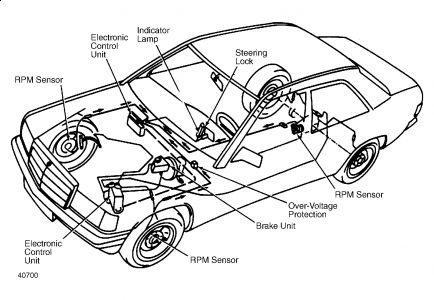
This car has an ABS system with 2 supply ports from the Master Cyl which supply hydraulic output ports 1 for the front Clprs & 1 for the rear Clprs.
The port from the Mstr Cyl that supplies the rear Clprs via the ABS unit is not supplying any pressure.
The front system works fine.
The Mstr Cyl was replaced recently & should be working properly.
Any suggestions?
Saturday, November 28th, 2009 AT 1:13 AM

3 Replies

Tiny
DAVE H
  • MECHANIC
  • 13,383 POSTS
Hello .. thanks for the donation .. much appreciated

Sounds like the solonoid valve for the rear brakes is not opening !!

HYDRAULIC UNIT
Independent of master cylinder pressure, hydraulic unit will compensate brake fluid pressure to wheel cylinders during regulation. Pressure increase above master cylinder pressure is not possible.
The 3 hydraulic unit solenoid valves control left front, right front and rear brakes. By activating valves with current of varying amperage, brake fluid pressure in individual calipers may be increased, held or decreased.
In pressure "build-up" stage, pressure increases by opening intake valve to pressure supplied by master cylinder. In pressure "holding" stage, which precedes "reduction" stage, pressure from hydraulic unit to wheels is constant. Output and input valves in solenoid valve are closed.
During pressure "reduction" stage, brake fluid flows from reservoir to return pump. To maintain fluid volume, pump returns fluid to main cylinder against prevailing pressure.
To dampen delivery noise, each circuit has a silencer. Relays for solenoid valves and return pump are on 12-pole socket of hydraulic unit. A diode is soldered in socket. Hydraulic unit is connected to ground by cable.
Fig. 1: Mercedes-Benz Automatic Brake System Component Location


https://www.2carpros.com/forum/automotive_pictures/266999_merc_3.jpg


Hope this helps


https://www.2carpros.com/forum/automotive_pictures/266999_AAA2_369.png

Was this
answer
helpful?
Yes
No
Saturday, November 28th, 2009 AT 5:42 AM
Tiny
RKB13
  • MEMBER
  • 2 POSTS
Your answer indicated the solenoid valve for the rear brakes is not opening.
OK, I assume these Solenoid Valves are located in the ABS Hydraulic Unit mounted in the left fwd area of the Engine compartment (as identified in your diagram in this area as the Electronic Control Unit).
Assuming this is the location of the Solenoid Valves I have a few questions:
1) Is there a way of isolating the problem between the Solenoid Valves, ABS Control Module & the Overload Protection Relay Module?
2) Are these Solenoid Valves part of an assembly of the ABS Hydraulic Unit?
In other words can they be removed, tested &/or replaced as needed in the ABS Hydraulic Unit?
Are there any pictures showing the assembly with its associated parts & how they go together?
3) Are there special procedures to follow for bleeding the system that I may have overlooked?
4) If the Solenoid Valves are found to be inoperative can they be replaced individually or does the entire ABS Hydraulic Unit need replacement?
5) I have looked around for replacement parts on the internet to no avail! Do you have any suggestions?
Rich
Was this
answer
helpful?
Yes
No
+1
Saturday, November 28th, 2009 AT 6:54 PM
Tiny
DAVE H
  • MECHANIC
  • 13,383 POSTS
The ABS Hydraulic control unit can only be tested with a special ABS tester from M/B and can only be replaced as a UNIT you cannot break it down to check it works ! .. I have a dealer part price for the ABS Hydraulic Unit of $2000.00 ... so you may want to look aftermarket/reconditioned or from a car recycle yard

TESTING WITH ABS TESTER
NOTE:DO NOT drive vehicle with tester connected.

Connecting Tester
With ignition off, disconnect 35-pole connector of cable harness from electronic control unit.
Connect 35-pole connector to plug of ABS Test Adaptor (126-589-09-21-00). Make sure that all other electrical components are off before turning ignition on.
Connect multimeter to test adapter. This adapter permits testing the complete ABS system, except the electronic control unit.

TEST 8
Testing Internal Resistance Of Solenoid Valves

Set multimeter to "OHMS" position. Ignition off. Push ground button. Rotary switch moved successively to positions 8, 9 and 10.
Resistance should be 0.7-1.7 ohms. If internal resistance is under .07 ohms or over 1.7 ohms, go to step 3).
Check for poor contact at plug connector on hydraulic unit, interrupted connecting wires or defective hydraulic unit.

TEST 9
Testing Pressure Holding Of Solenoid Valves

Ignition on. Rotary switch moved successively to positions 8, 9 and 10. Spin respective wheel. Press "P" push button. Actuate brake pedal.
Wheel should permit turning and no brake force should build up. If not okay, go to step 3).
Check for defective motor relay, return pump, or solenoid valve. Replace as necessary.

TEST 10
Testing Pressure Reduction Of Solenoid Valve

Ignition on. Rotary switch moved successively to positions 8, 9 and 10. Actuate brake pedal. Press "P" button. Turn respective wheel.
Introduced brake force should be reducing. Return pump should be running. If not, proceed to step 3).
Check for defective motor relay, return pump, or solenoid valve. Replace as necessary.

TEST 11
NOTE:Stoplight switch is connected to 35-pole plug at pin 25.

Testing Overvoltage Protection Relay
Ignition on. Actuate brake pedal. LED indicator "0" should come on. If not, check connecting wires or replace stoplight switch.

****MANUAL BLEEDING
On Isuzu and Jaguar models, start engine and run at idle. On all other models, exhaust all vacuum from power unit by depressing brake pedal several times.
Fill master cylinder, then install clear vinyl bleeder hose onto first bleeder valve to be serviced.
NOTE:On manual transmission vehicles where clutch master cylinder feeds from brake master cylinder, bleed clutch cylinder first.

Place other end of hose in clear glass jar.
3) Partially fill jar with clean brake fluid, so end of hose is submerged in fluid. Open bleeder valve 1-2 turns. Depress brake pedal slowly through its full travel.
4) Close bleeder valve, then release pedal. Pump pedal several times to push air toward wheel cylinders. Repeat procedure until flow of brake fluid is clear, and shows no signs of air bubbles. Proceed to next bleeder valves.
NOTE:Check fluid level in master cylinder frequently during the bleeding sequence.

hope this helps


https://www.2carpros.com/forum/automotive_pictures/266999_AAA2_611.png

Was this
answer
helpful?
Yes
No
Thursday, December 3rd, 2009 AT 4:50 AM

Please login or register to post a reply.

Sponsored links