Welcome to 2CarPros.
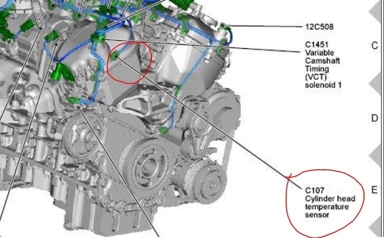
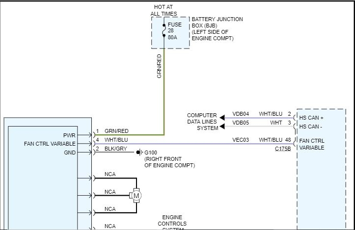
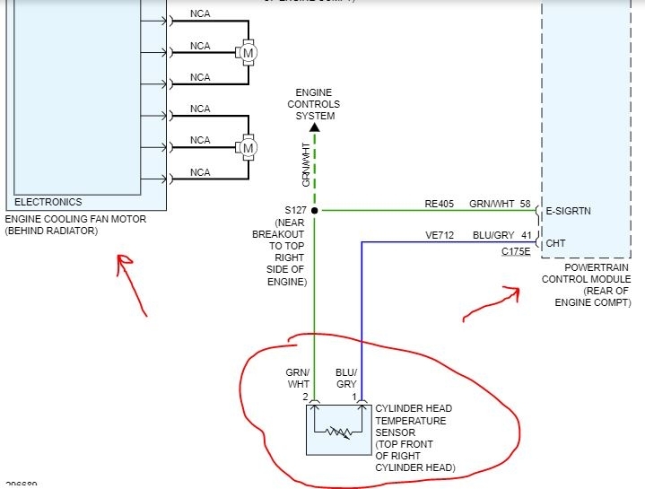
This vehicle has a cylinder head temperature sensor (CHT) which signals the computer. The bad news is you have to remove the intake manifold to access it. It is located under it. Picture 1 shows its location.
Here are the directions for removing the lower intake manifold. Sensor replacement will follow. All attached pictures correlate with these directions.
__________________________________________
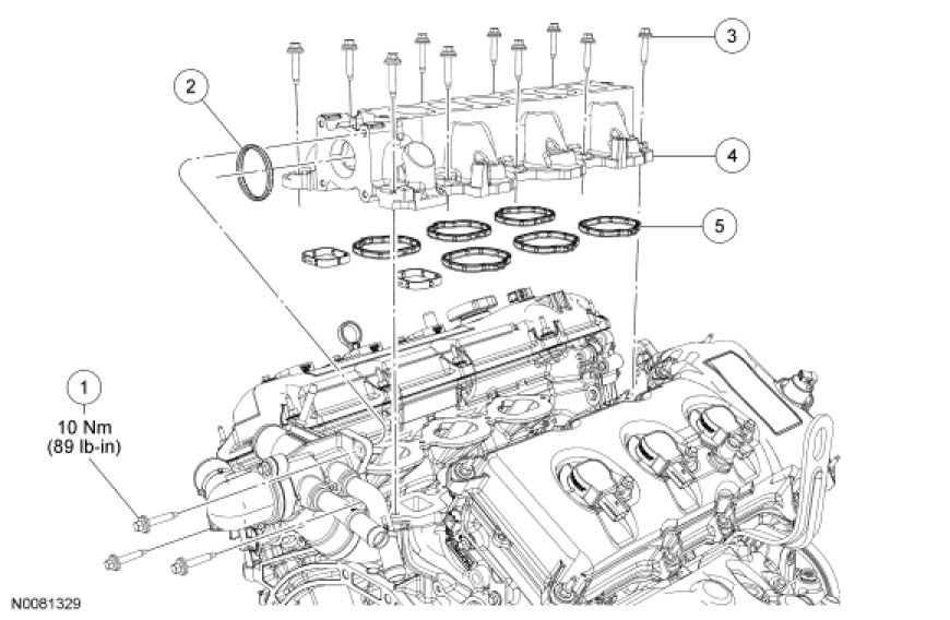
See Picture 2
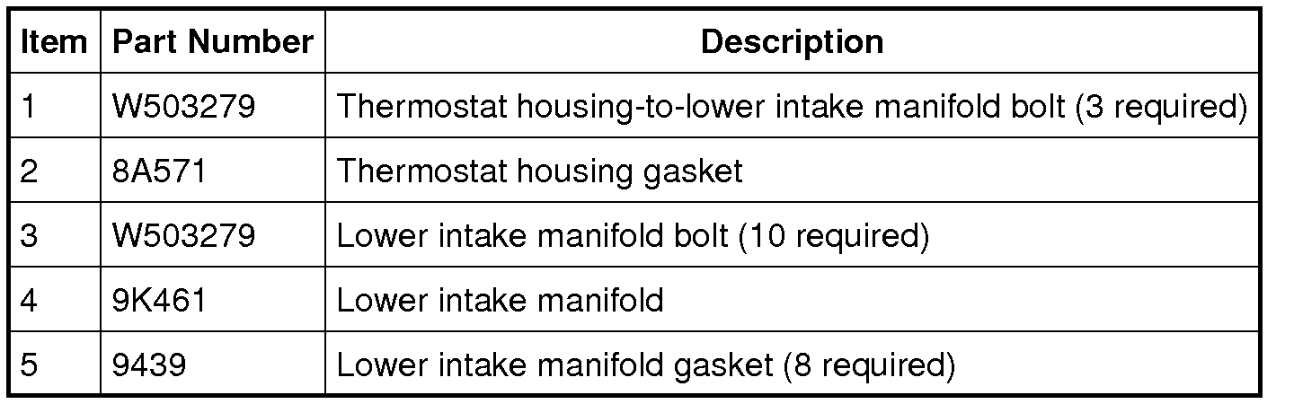
See Picture 3
Removal
NOTICE: During engine repair procedures, cleanliness is extremely important. Any foreign material, including any material created while cleaning gasket surfaces that enters the oil passages, coolant passages or the oil pan, may cause engine failure.
1. Remove the fuel rail.
2. Drain the cooling system.
3. Remove the 3 thermostat housing-to-lower intake manifold bolts.
4. Remove the 10 bolts and the lower intake manifold.
- Remove and discard the intake manifold and thermostat housing gaskets.
- Clean and inspect all sealing surfaces.
Installation
1. NOTICE: If the engine is repaired or replaced because of upper engine failure, typically including valve or piston damage, check the intake manifold for metal debris. If metal debris is found, install a new intake manifold. Failure to follow these instructions can result in engine damage.
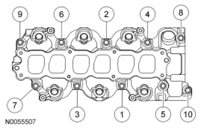
Using new intake manifold and thermostat housing gaskets, install the lower intake manifold and the 10 bolts.
- Tighten in the sequence shown to 10 Nm (89 lb-in).
See Picture 4
2. Install the 3 thermostat housing-to-lower intake manifold bolts.
- Tighten to 10 Nm (89 lb-in).
3. Install the fuel rail.
4. Fill and bleed the cooling system.
_______________________________________________
Sensor Replacement
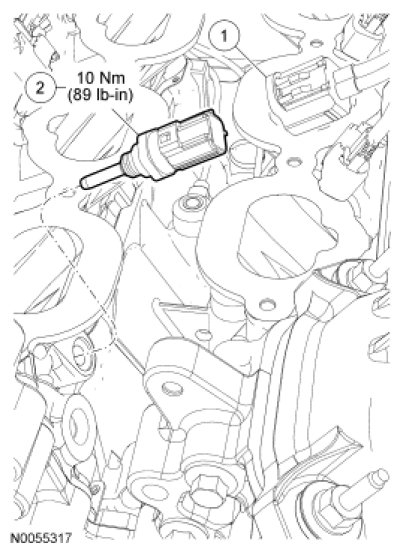
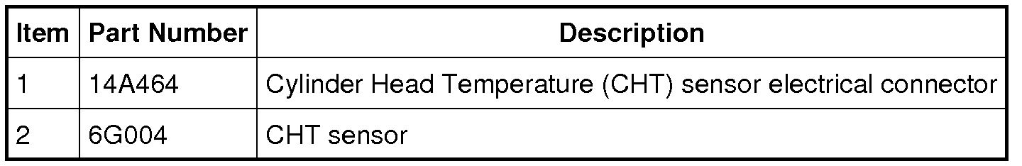
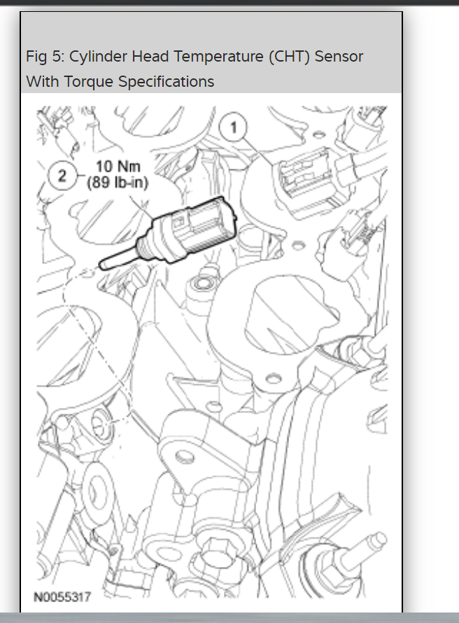
Cylinder Head Temperature (CHT) Sensor
Picture 5
Picture 6
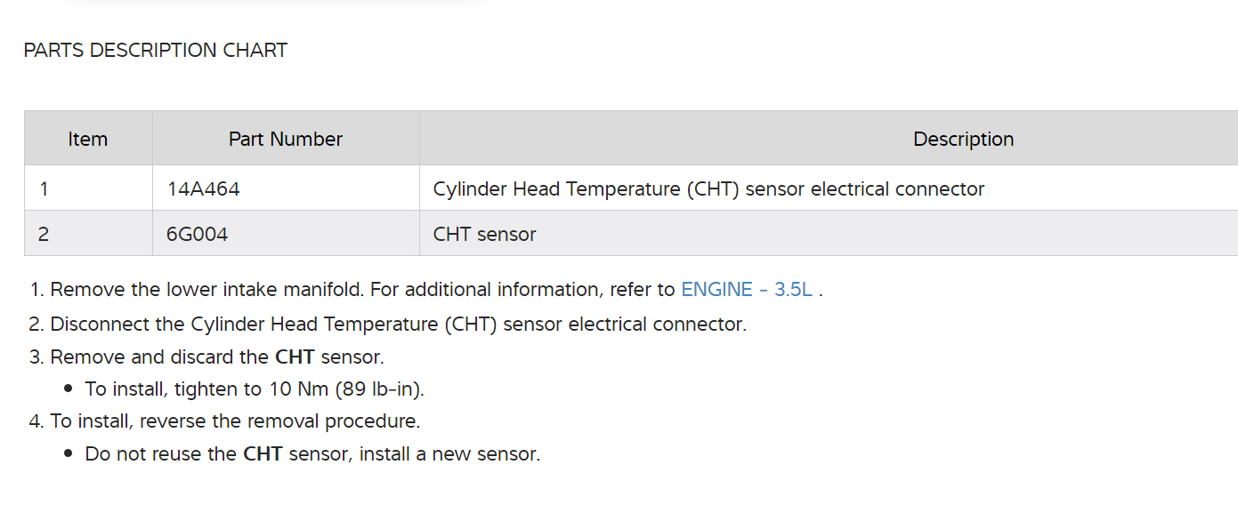
1. Remove the lower intake manifold.
2. Disconnect the Cylinder Head Temperature (CHT) sensor electrical connector.
3. Remove and discard the CHT sensor.
- To install, tighten to 10 Nm (89 lb-in).
4. To install, reverse the removal procedure.
- Do not reuse the CHT sensor, install a new sensor.
___________________________________________
Let me know if this helps or if you have other questions.
Take care,
Joe
Images (Click to enlarge)
Jun 7, 2019 at 10:30 PM