Since it is timed like you mentioned, I suspect the module has failed. I have the diagnostics to check it. I will add them here. They are somewhat involved.
___________________________________________
"LOW LINE" CENTRAL TIMER MODULE (CHIME) TEST
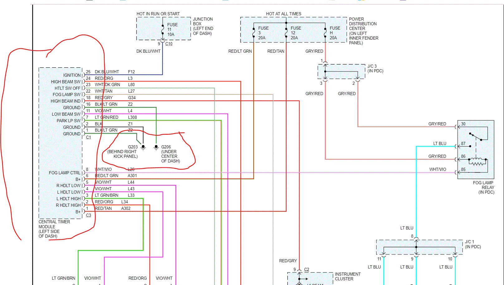
For additional information on the Central Timer Module, refer to Powertrain Management / Computers and Control Systems / Body Control Module. See: Body Control Module > Testing and Inspection
The hard wired inputs to and outputs from the Central Timer Module (CTM) may be diagnosed and tested using conventional diagnostic tools and methods.
However, conventional diagnostic methods may not prove conclusive in the diagnosis of the CTM. In order to obtain conclusive testing of the CTM, the Programmable Communications Interface PCI data bus network and all of the electronic modules that provide inputs to or receive outputs from the CTM must also be checked. The most reliable, efficient, and accurate means to diagnose the CTM, the PCI data bus network, and the electronic modules that provide inputs to or receive outputs from the CTM requires the use of a DRB III scan tool. Refer to the appropriate diagnostic information. The DRB III scan tool can provide confirmation that the PCI data bus network is functional, that all of the electronic modules are sending and receiving the proper messages over the PCI data bus, and that the CTM is receiving the proper hard wired inputs and responding with the proper hard wired outputs needed to perform its many functions.
WARNING: ON VEHICLES EQUIPPED WITH AIRBAGS, DISABLE THE AIRBAG SYSTEM BEFORE ATTEMPTING ANY STEERING WHEEL, STEERING COLUMN, SEAT BELT TENSIONER, OR INSTRUMENT PANEL COMPONENT DIAGNOSIS OR SERVICE. DISCONNECT AND ISOLATE THE BATTERY NEGATIVE (GROUND) CABLE, THEN WAIT TWO MINUTES FOR THE AIRBAG SYSTEM CAPACITOR TO DISCHARGE BEFORE PERFORMING FURTHER DIAGNOSIS OR SERVICE. THIS IS THE ONLY SURE WAY TO DISABLE THE AIRBAG SYSTEM. FAILURE TO TAKE THE PROPER PRECAUTIONS COULD RESULT IN ACCIDENTAL AIRBAG DEPLOYMENT AND POSSIBLE PERSONAL INJURY.
NOTE: The following tests may not prove conclusive in the diagnosis of the Central Timer Module (CTM). The most reliable, efficient, and accurate means to diagnose the CTM requires the use of a DRB III scan tool. Refer to the appropriate diagnostic information.
1. Check the fused B(+) fuses (Fuse 3 - 20 ampere, and Fuse 12 - 20 ampere) in the Power Distribution Center (PDC). If OK, go to Step 2. If not OK, repair the shorted circuit or component as required and replace the faulty fuse.
2. Check for battery voltage at the fused B(+) fuses (Fuse 3 - 20 ampere, and Fuse 12 - 20 ampere) in the PDC. If OK, go to Step 3. If not OK, repair the open B(+) circuit between the PDC and the battery as required.
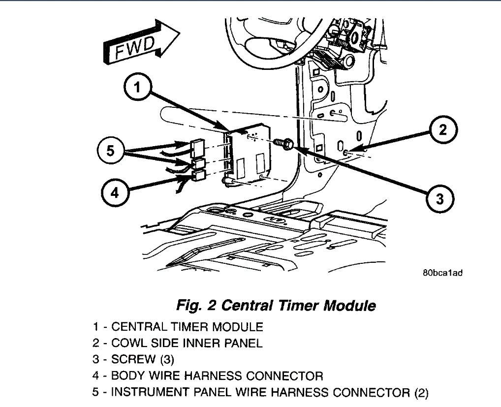
3. Disconnect and isolate the battery negative cable. Disconnect the instrument panel wire harness connector (Connector C3) for the CTM from the CTM connector receptacle. Reconnect the battery negative cable. Check for battery voltage at each of the two fused B(+) circuit cavities of the instrument panel wire harness connector (Connector C3) for the CTM. If OK, disconnect and isolate the battery negative cable, reconnect the instrument panel wire harness connector (Connector C3) for the CTM to the CTM connector receptacle, and go to Step 4. If not OK, repair the open fused B(+) circuit(s) between the CTM and the PDC as required.
4. Check the fused ignition switch output (run- start) fuse (Fuse 11 - 10 ampere) and the fused ignition switch output (run-acc) fuse (Fuse 5 - 20 ampere) in the Junction Block (JB). If OK, go to Step 5. If not OK, repair the shorted circuit or component as required and replace the faulty fuse(s).
5. Reconnect the battery negative cable. Turn the ignition switch to the ON position. Check for battery voltage at the fused ignition switch output (run-start) fuse (Fuse 11 - 10 ampere) and the fused ignition switch output (run-acc) fuse (Fuse 5 - 20 ampere) in the JB. If OK, go to Step 6. If not OK, repair the open fused ignition switch output (run-start) circuit or fused ignition switch output (run-acc) circuit between the JB and the ignition switch as required.
6. Turn the ignition switch to the OFF position. Disconnect and isolate the battery negative cable. Disconnect the instrument panel wire harness connector (Connector C1) for the CTM from the CTM connector receptacle. Reconnect the battery negative cable. Turn the ignition switch to the ON position. Check for battery voltage at the fused ignition switch output (run-start) circuit cavity and the fused ignition switch output (run-acc) cavity of the instrument panel wire harness connector (Connector C1) for the CTM. If OK, go to Step 7. If not OK, repair the open fused ignition switch output (run-start) circuit or fused ignition switch output (run-acc) circuit between the CTM and the JB as required.
7. Turn the ignition switch to the OFF position. Check for continuity between each of the three ground circuits in the instrument panel wire harness connector (Connector C1) for the CTM and a good ground. In each case there should be continuity. If OK, use a DRB III scan tool to perform further diagnosis of the CTM. Refer to the appropriate diagnostic information. If not OK, repair the open ground circuit(s) to ground (G207 or G208) as required.
__________________
Let me know if that helps or makes things worse. LOL
Joe
Jul 12, 2020 at 9:05 PM