Hi and thanks for using 2CarPros.com.
It is possible. However, I would recommend requesting the valve cover be returned so you can see it or replace it yourself. It is a bit of work, but not too bad.
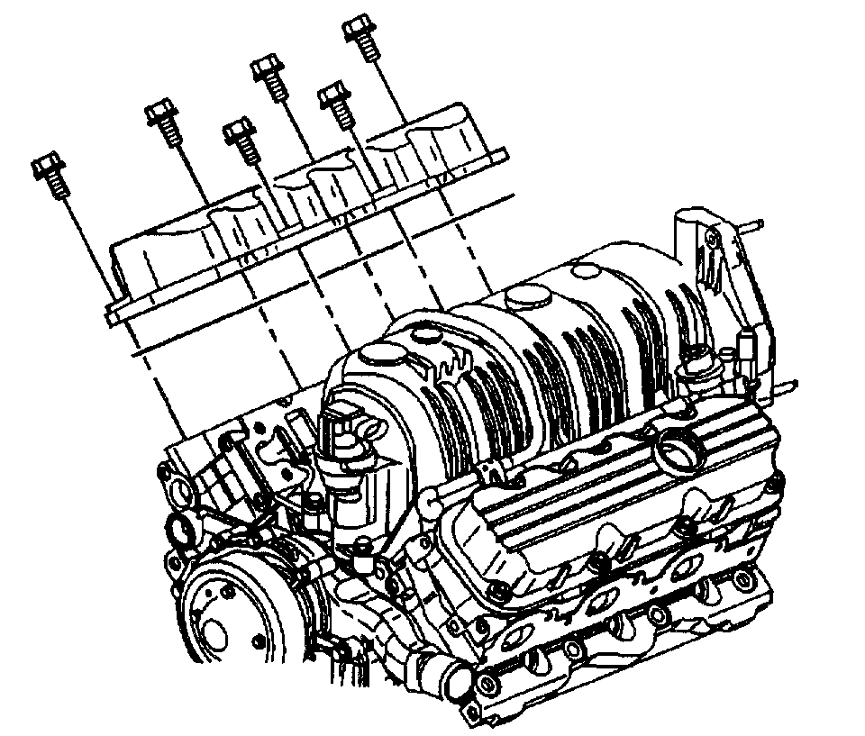
Here are the directions. Also, you inspect it yourself to see where the leak is coming from. At the end of the directions, I attached a picture so you can see how it comes off. Also, here is a link that shows belt routing for your vehicle. I am adding it so you can locate the alternator. There are a couple placed it could be, but if you look at the pictures on the link, it will help find it.
https://www.2carpros.com/diagrams/chevrolet/monte-carlo/2000
_______________________
Removal Procedure
- Tools Required
- J 41131 Engine Tilt Strap
1. Remove the fuel injector sight shield. Refer to Fuel Injector Sight Shield Replacement.
2. Remove the generator. Refer to Generator Replacement.
3. Remove the tensioner bracket. Refer to Drive Belt Tensioner Replacement.
4. Remove the AIR valve/pipe, if equipped. Refer to Secondary AIR Injection Combination Valve/Pipe Replacement in Computers and Controls.
5. Rotate the engine for access:
5.1.Disconnect the throttle body air inlet duct.
5.2.Remove the engine mount strut bolts. Rotate the engine mount struts aside. Refer to Engine Mount Strut Replacement (Left) and Engine Mount Strut Replacement (Right).
5.3.Disconnect the AIR pipe, if necessary. Refer to Secondary AIR Injection Combination Valve/Pipe Replacement in Computers and Controls.
5.4.Apply the parking brake.
5.5.Put the transaxle in Neutral.
5.6.Install the J41131.
5.7.Rotate the engine forward for component access.
6. Remove the fuel injector sight shield bracket.
7. Remove the right (rear) spark plug wires. Refer to Spark Plug Wire Harness Replacement in Powertrain Management.
8. Remove the EVAP purge valve and the brace. Refer to EVAP Canister Purge Valve Replacement in Computers and Controls.
9. Remove the right (rear) valve rocker arm cover bolts.
Important: If the valve rocker arm cover adheres to the cylinder head, remove the valve rocker arm cover by bumping the end of the valve rocker arm cover with the palm of your hand or a soft rubber mallet.
10. Remove the right valve rocker arm cover.
11. Remove the right valve rocker arm cover gasket.
12. Clean the sealing surface on the cylinder head and the valve rocker arm cover with a degreaser.
13. Clean the valve rocker arm cover bolts of all thread locking adhesive.
Installation Procedure
1. Install the new valve rocker arm cover gasket. Make sure that the valve rocker arm cover gasket is seated properly in the valve rocker arm cover groove.
2. Install the right valve rocker arm cover.
3. Apply thread lock compound GM P/N 1234593 or equivalent to the valve rocker arm cover bolt threads.
Notice: Refer to Fastener Notice in Service Precautions.
4. Install the right valve rocker arm cover bolts.
Tighten the right valve rocker arm cover bolts to 10 Nm (89 inch lbs.).
5. Install the EVAP purge solenoid and the brace. Refer to EVAP Canister Purge Valve Replacement in Computers and Controls.
6. Install the right spark plug wires. Refer to Spark Plug Wire Harness Replacement in Powertrain Management.
7. Install the fuel injector sight shield bracket.
8. Return the engine to the proper position:
8.1.Carefully release the J41131. Carefully return the engine to the proper position.
8.2.Put the transaxle in Park.
8.3.Release the parking brake.
8.4.Connect the AIR pipe, if necessary. Refer to Secondary AIR Injection Combination Valve/Pipe Replacement in Computers and Controls.
8.5.Install the engine mount struts. Refer to Engine Mount Strut Replacement (Left) and Engine Mount Strut Replacement (Right).
8.6.Connect the throttle body air inlet duct.
9. Install the engine mount struts. Refer to Engine Mount Strut Replacement (Left) and Engine Mount Strut Replacement (Right).
10. Install the AIR valve/pipe, if equipped. Refer to Secondary AIR Injection Combination Valve/Pipe Replacement in Computers and Controls.
11. Install the tensioner bracket. Refer to Drive Belt Tensioner Replacement.
12. Install the generator. Refer to Generator Replacement in Starting and Charging.
13. Install the fuel injector sight shield. Refer to Fuel Injector Sight Shield Replacement.
14. Check for proper fluid levels.
15. Check for oil leaks.
Let me know if this helps or if you have other questions.
Take care,
Joe
Nov 16, 2018 at 6:09 PM