Lets forget about previous work and start with this.
HOW TO USE THE SELF-DIAGNOSTIC FUNCTION
The HVAC control unit has a self-diagnostic function for heating, ventilation, and air conditioning system. To run the self-diagnostic function, do the following:
1. Turn the ignition switch to LOCK (0).
2. Press and hold the recirculation control and rear window defogger buttons, turn the ignition switch to ON (II).
3. The recirculation indicator turns on for 2 seconds, then the self-
diagnostic function begins.
NOTE:
The blower motor will run at various speeds when in the self-diagnostic mode.
In the case of multiple problems, the recirculation
indicator will blink the lowest number DTC only.
If no DTCs are found, the indicator will not blink.
DTC INDICATOR 6: A PROBLEM IN THE BLOWER MOTOR CIRCUIT
1. Turn the ignition switch to LOCK (0), and then turn it to ON (II).
2. Do the self-diagnostic with the HVAC control unit.
3. Check for DTCs. Is DTC 6 indicated?
YES - Go to step 4.
NO - Intermittent failure. Check for loose wires or poor connections on the blower motor circuit.
4. Turn the ignition switch to LOCK (0).
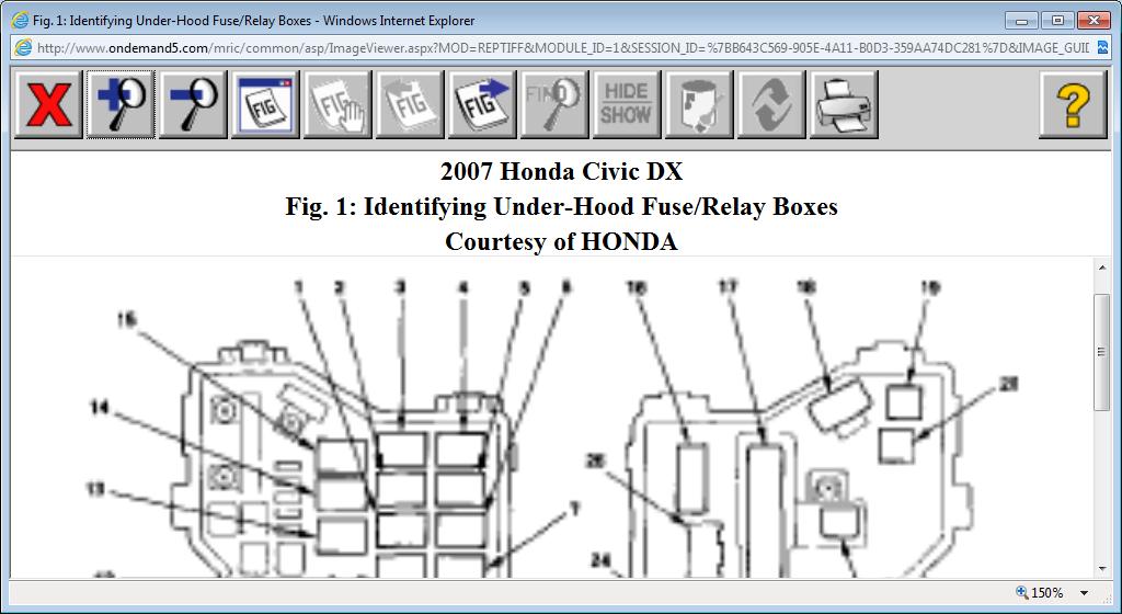
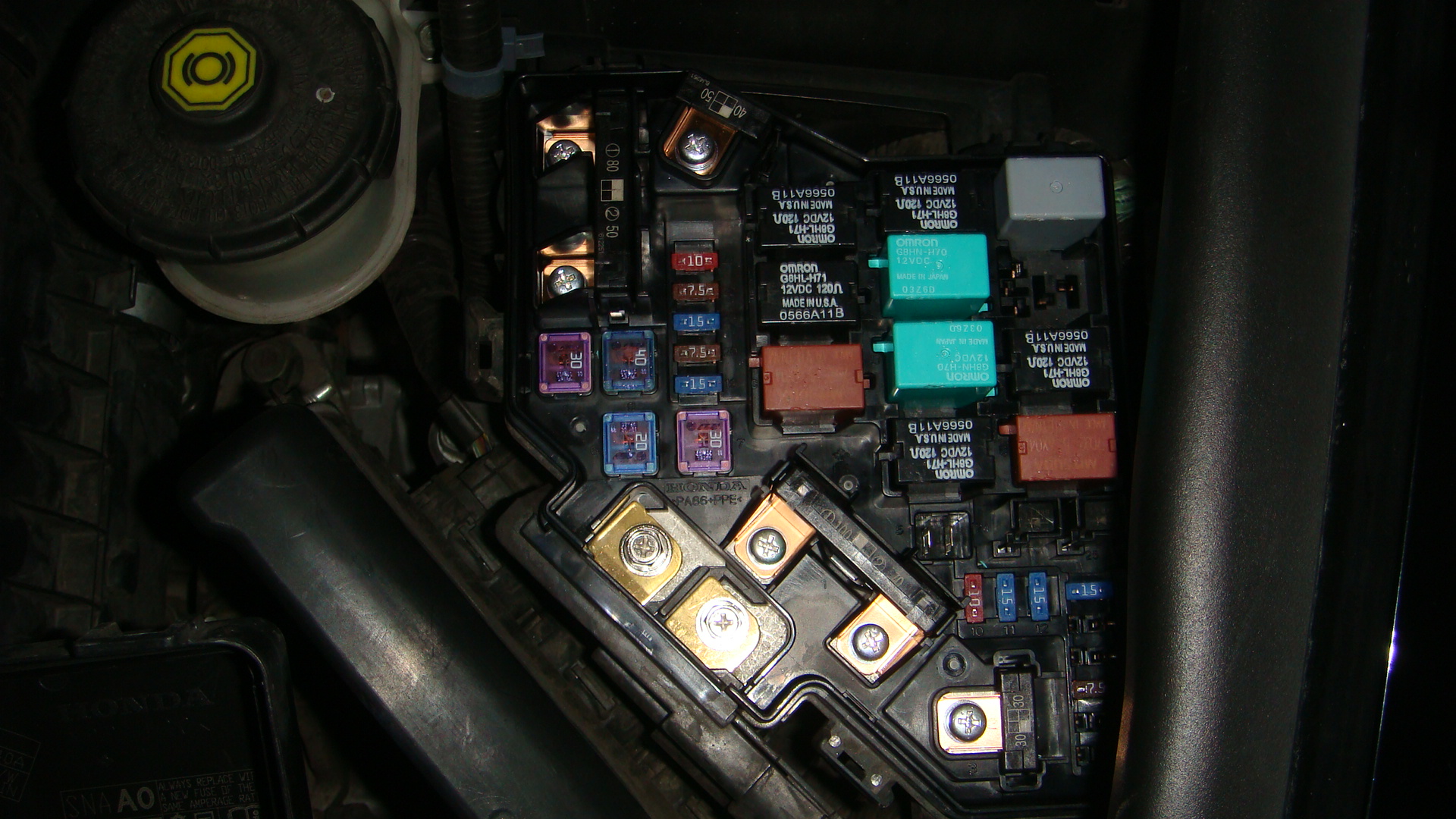
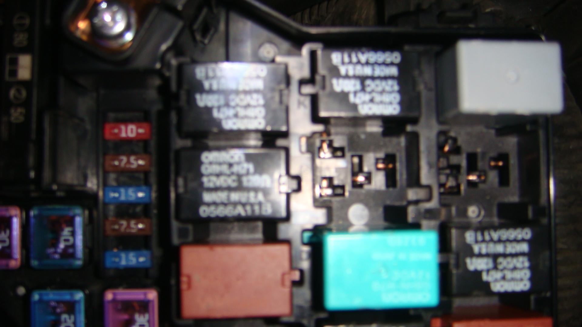
5. Check the No. 9 (40 A) fuse in the under-hood fuse/relay box, and the No. 36 (10 A) fuse in the under-dash fuse/relay box. Are the fuses OK?
YES - Go to step 6.
NO - Replace the fuses, and recheck. If the fuses blow again, check for a short in the No. 9 (40 A) and No. 36 (10 A) fuses circuit.
6. Connect the blower motor 2P connector terminal No. 2 to body ground with a jumper wire.
7. Turn the ignition switch to ON (II). Does the blower motor
run?
YES - Go to step 8.
NO - Go to step 24.
8. Turn the ignition switch to LOCK (0).
9. Disconnect the jumper wire.
10. Disconnect the power transistor 4P connector.
11. Check for continuity between the power transistor 4P connector terminal No. 2 and body ground.
Is there continuity?
YES - Go to step 12.
NO - Check for an open in the wire between the power transistor and body ground. If the wire is OK, check for poor ground at G401.
12. Connect the power transistor 4P connector terminals No. 2 and No. 4 with a jumper wire.
13. Turn the ignition switch to ON (II). Does the blower motor run at high speed?
YES - Go to step 14.
NO - Repair open in the wire between the power transistor and the blower motor.
14. Turn the ignition switch to LOCK (0).
15. Disconnect the jumper wire.
16. Disconnect the HVAC control unit 24P connector.
17. Check for continuity between body ground and the HVAC control unit 24P connector terminals No. 7 and No. 8 individually.
Is there continuity?
YES - Repair short to body ground in the wire(s) between the HVAC control unit and the power transistor.
NO - Go to step 18.
18. Check for continuity between the following terminals of the HVAC control unit 24P connector and the power transistor 4P connector.
24P: 4P:
No. 7 No. 3
No. 8 No. 1
Is there continuity?
YES - Go to step 19.
NO - Repair open in the wire(s) between the HVAC control unit and the power transistor.
19. Turn the ignition switch to ON (II).
20. Measure the voltage between body ground and the HVAC control unit 24P connector terminals No. 7 and No. 8 individually.
Is there voltage?
YES - Repair short to power in the wire(s).
NO - Go to step 21.
21. Turn the ignition switch to LOCK (0).
22. Reconnect the HVAC control unit 24P connector.
23. Test the power transistor.
Is the power transistor OK?
YES - Check for loose wires or poor connections at the HVAC control unit 24P connector and at the power transistor 4P connector. If the connections are good, substitute a known-good HVAC control unit, and recheck. If the symptom/indication goes away, replace the original HVAC control unit.
NO - Replace the power transistor.
24. Turn the ignition switch to LOCK (0).
25. Disconnect the jumper wire.
26. Disconnect the blower motor 2P connector.
27. Turn the ignition switch to ON (II).
28. Measure the voltage between the blower motor 2P connector ter
terminal No. 1 and body ground.
Is there battery voltage?
YES - Replace the blower motor.
NO - Go to step 29.
29. Turn the ignition switch to LOCK (0).
30. Remove the blower motor relay from the under-hood fuse/relay box, and test it.
Is the relay OK?
YES - Go to step 31.
NO - Replace the blower motor relay.
31. Measure the voltage between the blower motor relay 4P socket terminal No. 1 and body ground.
Is there battery voltage?
YES - Go to step 32.
NO - Replace the under-hood fuse/relay box.
32. Turn the ignition switch to ON (II).
33. Measure the voltage between the blower motor relay 4P socket terminal No. 3 and body ground.
Is there battery voltage?
YES - Go to step 34.
NO - Repair open in the wire between the No. 36 (10 A) fuse in the under-dash fuse/relay box and the blower motor relay.
34. Turn the ignition switch to LOCK (0).
35. Check for continuity between the blower motor relay 4P socket terminal No. 4 and body ground.
Is there continuity?
YES - Repair open in the wire between the blower motor relay and the blower motor.
NO - Check for an open in the wire between the blower motor relay and body ground. If the wire is OK, check for poor body ground at G301.
Sunday, September 29th, 2019 AT 9:41 AM
(Merged)