The vehicle listed above is a C1500, 2WD, 5.7L V8: All of the caution and warning and the turn signal indicator lights on the panel work fine; just the background lights are out.
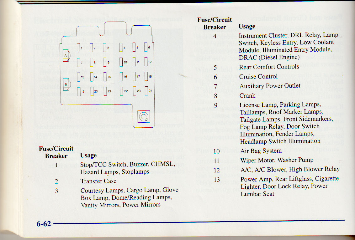
I pulled the instrument cluster and put battery power directly to the lighting circuit on the back of the cluster and all of the illumination lights light up and work fine. I also changed out the 11-terminal headlamp/instrument panel dimmer/dome Lamp switch (AC Delco Part Number D1523H, see the photo attached) that is on the left side of the dash but that did not fix the problem.
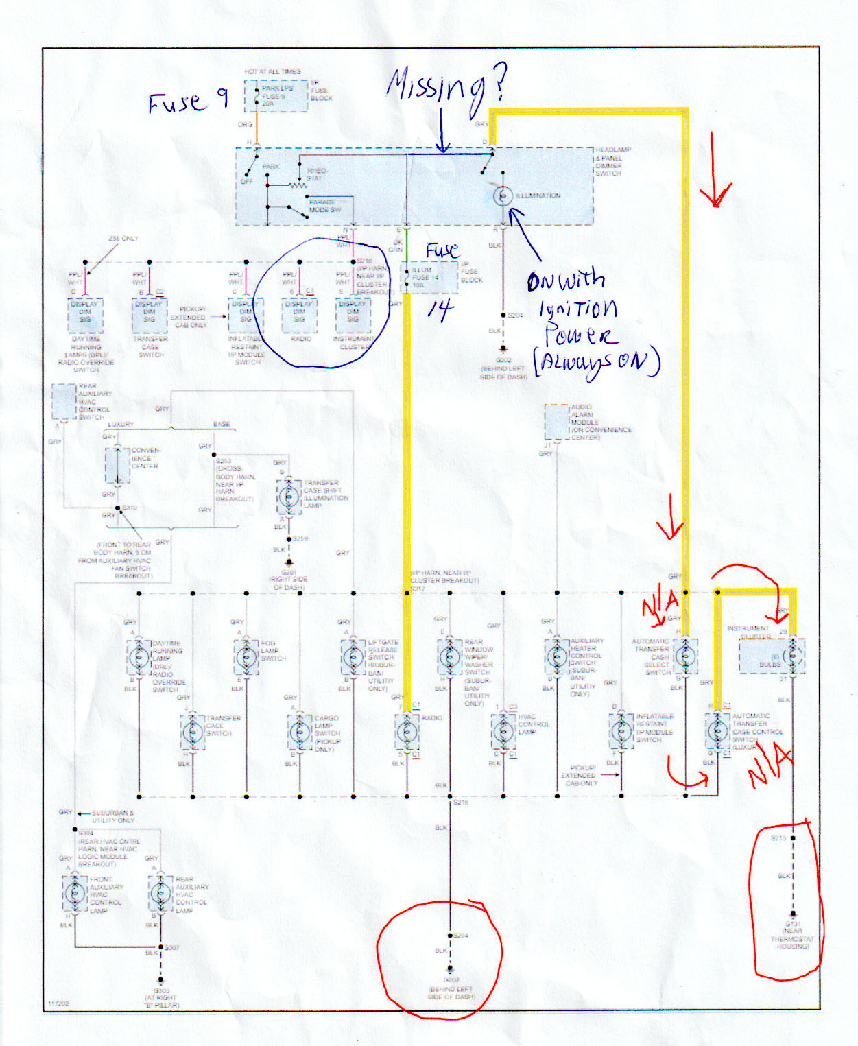
The radio/clock and the shift indicator lights work but when I rotate the dimmer control there is no dim control. They only work when the dim knob is rotated almost fully and just short of turning on the dome and interior lights, which also work when I rotate the dimmer all the way past the detent or click. The dome override works as well.
I searched YouTube for a video on this problem but they only address checking the instrument cluster and/or replacing the D1532H switch.
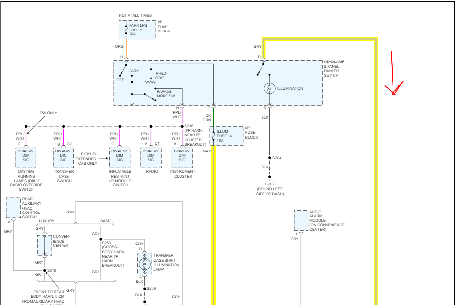
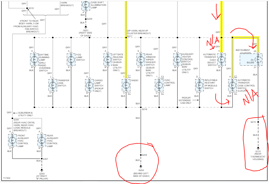
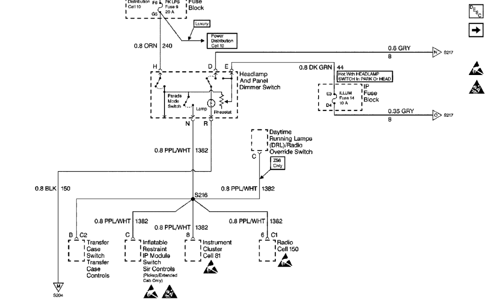
I am thinking that maybe the wire between the dimmer switch and the instrument cluster may be broken somehow but from what I can see of the harness without tearing things apart, it appears okay. I am still searching online for the correct wiring diagrams but have not as yet been successful. If you can provide a link to the correct diagrams that would be most helpful, and can you otherwise shed any light on the subject? No pun intended. Thanks much in advance.
M.
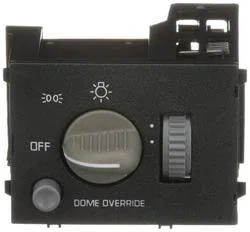
I pulled the instrument cluster and put battery power directly to the lighting circuit on the back of the cluster and all of the illumination lights light up and work fine. I also changed out the 11-terminal headlamp/instrument panel dimmer/dome Lamp switch (AC Delco Part Number D1523H, see the photo attached) that is on the left side of the dash but that did not fix the problem.
The radio/clock and the shift indicator lights work but when I rotate the dimmer control there is no dim control. They only work when the dim knob is rotated almost fully and just short of turning on the dome and interior lights, which also work when I rotate the dimmer all the way past the detent or click. The dome override works as well.
I searched YouTube for a video on this problem but they only address checking the instrument cluster and/or replacing the D1532H switch.
I am thinking that maybe the wire between the dimmer switch and the instrument cluster may be broken somehow but from what I can see of the harness without tearing things apart, it appears okay. I am still searching online for the correct wiring diagrams but have not as yet been successful. If you can provide a link to the correct diagrams that would be most helpful, and can you otherwise shed any light on the subject? No pun intended. Thanks much in advance.
M.
Image (Click to enlarge)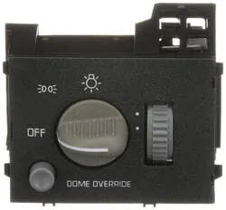
Apr 15, 2023 at 8:29 PM