CV axle and ball joints replacement instructions needed

Tiny
CORY2427
  • MEMBER
  • 2012 VOLKSWAGEN BEETLE
  • 2.5L
  • 5 CYL
  • 2WD
  • AUTOMATIC
  • 84,458 MILES
Have a bad popping when cut wheel deep and back out so on. So just bought ball joints and axles, even though there’s no slack. Need instructions step by step on how to change both and size tools I need.
Thursday, March 21st, 2019 AT 6:02 PM

7 Replies

Tiny
JACOBANDNICKOLAS
  • MECHANIC
  • 108,192 POSTS
Welcome to 2CarPros.

Here are the directions for removing the axle. The directions include removal of the lower ball joint. Tools needs are listed first. I will tell you that some of the axle nuts are a 32mm and others require an internal allen socket, which if I recall is 17mm. The nuts that hold the ball joint in place could be a 10mm or 13mm bolt. Truly, if they have ever been changed, different manufacturers supply new bolts and they come in different sized.

Here are the directions and the pictures attached correlate with the directions:

_______________________________________

Drive Axle, Removing and Installing, Triple Roller Joint AAR2600i

Special tools, testers and auxiliary items required

Drive Axle Wedge Tool (T10161)

Drive Shaft Remover (T10520)

Torque Wrench 1332 40-200Nm (VAG1332)

Removing

- Remove the drive axle bolt. Refer to [Drive Axle Threaded Connection, Loosening and Tightening ] See: Axle Shaft Assembly > Procedures > Drive Axle Threaded Connection, Loosening and Tightening.

The wheel bearing must not be under a load while the drive axle threaded connection on the wheel side is loose.

If the wheel bearings are under the load of the vehicle weight, the wheel bearing will be damaged. This reduces the service life of the wheel bearings.

The drive axle bolt may be loosened maximum 90° when the vehicle is standing on its wheels.

Vehicles without a drive axle must not be moved, otherwise the wheel bearing will be damaged. If a vehicle must be moved, be sure to note the following:

Install an outer joint in place of the drive axle.

Tighten the outer joint to 120 Nm.

- Loosen the wheel bolts.

- Raise the vehicle.

- Remove the wheel.

- Remove the lower noise insulation.

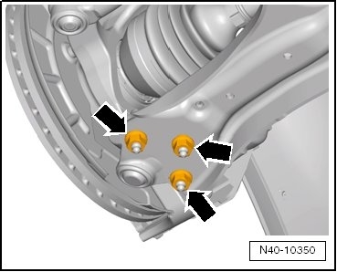
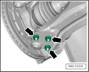
- Remove the nuts - arrows -.

Picture 1

- Remove both the wheel bearing housing and ball joint from the control arm.

- Pull drive axle out from wheel hub and secure it to body.

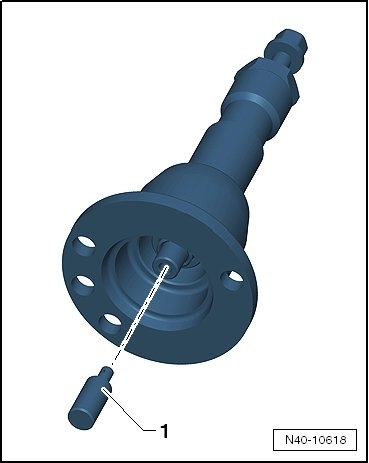
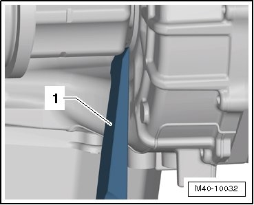
If the Drive Axle Cannot Be Pulled out of the Wheel Bearing, Then Drive Axle Can Be Pushed Out of the Wheel Bearing Using the Drive Shaft Remover (T10520).

Before using the Drive Shaft Remover (T10520), make sure that the thrust piece - 1 - is installed.

Picture 2

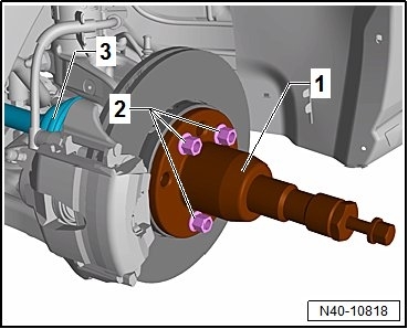
Using the Drive Shaft Remover (T10520) :

picture 3

- Secure the Drive Shaft Remover (T10520) - 1 - with three wheel bolts - 2 - on the wheel hub, so that the drive axle - 3 - can be pressed out.

- Follow the specified sequence.
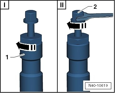
Picture 4

I Tighten the knurled nut - 1 - hand-tight.
II Only turn the bolt - 2 - using a wrench and press out the drive axle using the Drive Shaft Remover (T10520).

At the end of the tasks or to set back, the spindles must be brought back into the original position so that the hydraulic operation can be used.

- Place the Drive Axle Wedge Tool (T10161) - 1 - between the transmission housing and the triple roller joint.

- Using a rubber hammer, hit the inner joint on the Drive Axle Wedge Tool (T10161) and remove it from the transmission.

- Remove the drive axle.

Picture 5

Installing

Install in reverse order of removal. Note the following:

- Install new circlip into the groove of the joint shank.

- Engage the outer and inner splines of joint and transmission.

- Grab the drive axle by hand and push it into the joint up to the stop.

- Now slide joint piece into transmission with a tug.

The sliding part inside the linkage can be used for this tug. When doing this, do not pull the drive axle too far out of the joint.

Never use a hammer or mallet!

- Make sure the drive axle fits securely inside the transmission. The joint pulls against the resistance of the circlip.

When Checking, Only Pull on the Joint Piece and Not on the Drive Axle.

- Install the outer joint as far as possible into the wheel hub splines.

- Install the lower noise insulation.

- Attach the ball joint to the control arm - arrows -.

Picture 6

Make sure the ball joint boot is not damaged or twisted.

- Tighten drive axle bolt onto the wheel hub. Refer to [Drive Axle Threaded Connection, Loosening and Tightening ] See: Axle Shaft Assembly > Procedures > Drive Axle Threaded Connection, Loosening and Tightening.

Vehicle must not be standing on its wheels when doing this, otherwise wheel bearing will be damaged.

- Install the wheel and tighten. Refer to [Wheel Bolt Tightening Specifications ] See: Wheels and Tires > Mechanical > Wheel Bolt Tightening Specifications.

Tightening Specifications

Refer to [Overview - Lower Control Arm and Ball Joint ] See: Control Arm > Removal and Replacement > Overview - Lower Control Arm and Ball Joint

Refer to [Overview - Drive Axle ] See: Axle Shaft Assembly > Removal and Replacement > Overview - Drive Axle

Noise insulation bolts.

_________________________

Let me know if this helps or if you have other questions.

Take care,
Joe
Was this
answer
helpful?
Yes
No
Thursday, March 21st, 2019 AT 8:28 PM
Tiny
CORY2427
  • MEMBER
  • 270 POSTS
Do you have to have all these special tools to get it out?
Was this
answer
helpful?
Yes
No
Friday, March 22nd, 2019 AT 4:38 AM
Tiny
CORY2427
  • MEMBER
  • 270 POSTS
That axle remover is $500.00.
Was this
answer
helpful?
Yes
No
Friday, March 22nd, 2019 AT 4:41 AM
Tiny
CORY2427
  • MEMBER
  • 270 POSTS
If I took it to the shop they wouldn’t have these around here.
Was this
answer
helpful?
Yes
No
Friday, March 22nd, 2019 AT 5:10 AM
Tiny
JACOBANDNICKOLAS
  • MECHANIC
  • 108,192 POSTS
As far as the axle puller, you should be able to get it out without one. Don't strike the axle with a metal hammer. If the axle doesn't want to move, I have gently bumped the axle inward from the hub using an air impact hammer. If you just bump it a couple times with that, it should come out for you.
Was this
answer
helpful?
Yes
No
Friday, March 22nd, 2019 AT 8:42 PM
Tiny
CORY2427
  • MEMBER
  • 270 POSTS
Can you send me torque specs on axle nuts and ball joint, also sway bar links?
Was this
answer
helpful?
Yes
No
Sunday, March 24th, 2019 AT 9:30 PM
Tiny
JACOBANDNICKOLAS
  • MECHANIC
  • 108,192 POSTS
Welcome back:

Here are the directions for the axle nut. Picture 1 correlates with these directions.

__________________________________________________
Twelve-Point Bolt, Installing

Replace the twelve-point bolt.

The wheels must not be touching the ground when tightening the drive axle. Otherwise, wheel bearing may be pre-damaged.

Press the brake pedal. A second technician will be needed.

Tighten the twelve-point bolt to 200 Nm.

Lower the vehicle onto its wheels.

Turn the twelve-point bolt an additional 180°.

___________________________________________________

Here are the specs for all other steering and suspension components. See picture 2 for part identification.

1 Bolts

15 Nm +90°

Replace after removing

2 Front Body

3 Suspension Strut

Removing and installing. Refer to [Suspension Strut, Removing and Installing ] See: Suspension Strut / Shock Absorber > Removal and Replacement > Suspension Strut and Upper Control Arm.

4 Nut

65 Nm

5 Internal Multipoint Bolt

Bolt point must face in direction of travel.

6 Nut

70 Nm +90°

Replace after removing

7 Wheel Bearing Housing

Removing and installing. Refer to [Wheel Bearing Housing, Removing and Installing ] See: Wheel Bearing > Removal and Replacement > Wheel Bearing Housing, Removing and Installing.

If the wheel bearing housing must be replaced, alignment must be checked afterwards. Refer to [Vehicle Alignment ].

There are different versions.

Allocation. Refer to the Parts Catalog.

8 Nut

60 Nm

9 Ball Joint

Check. Refer to [Ball Joint, Checking ] See: Ball Joint > Component Tests and General Diagnostics > Ball Joint, Checking.

Removing and installing. Refer to [Ball Joint, Removing and Installing ] See: Ball Joint > Removal and Replacement > Ball Joint, Removing and Installing.

Replace with the control arm if damaged.

10 Nut

100 Nm

Always tighten the threaded connections in curb weight position. Refer to [Wheel Bearing in Curb Weight, Rear Axle, Lifting Vehicles with Coil Spring ] See: Steering and Suspension > Components > Wheel Bearing in Curb Weight, Rear Axle, Lifting Vehicles with Coil Spring.

11 Control Arm

Replace with the ball joint if damaged.

Removing and installing. Refer to [Lower Control Arm, Removing and Installing, Basis ] See: Control Arm > Removal and Replacement > Lower Control Arm, Removing and Installing, Basis.

Removing and installing (left side of the vehicle with a DSG(R) transmission or automatic transmission). Refer to [Lower Control Arm, Removing and Installing, On Left Side, Vehicles with DSG(R) or Automatic Transmission ] See: Control Arm > Removal and Replacement > Lower Control Arm, Removing and Installing, On Left Side, Vehicles with DSG(R) or Automatic Transmission.

12 Front Bonded Rubber Bushing

Removing and installing. Refer to [Lower Control Arm Bonded Rubber Bushing, Replacing, Front Bonded Rubber Bushing ] See: Control Arm Bushing > Removal and Replacement > Lower Control Arm Bonded Rubber Bushing, Replacing, Front Bonded Rubber Bushing.

13 Rear Bonded Rubber Bushing

Removing and installing. Refer to [Lower Control Arm Bonded Rubber Bushing, Rear Bonded Rubber Bushing, Replacing ] See: Control Arm Bushing > Removal and Replacement > Lower Control Arm Bonded Rubber Bushing, Rear Bonded Rubber Bushing, Replacing.

14 Coupling Rod

______________________________

All the above torque specs are listed in Newton Meter (Nm). If needed, they can be converted into inch pound or foot pounds using a conversion chart online.

Let me know if this helps.

Take care,
Joe
Was this
answer
helpful?
Yes
No
Monday, March 25th, 2019 AT 6:04 PM

Please login or register to post a reply.

Sponsored links