Ignition coil wiring

Tiny
FANTASTECH
  • MEMBER
  • 1979 JEEP CJ5
  • 3.8L
  • 4 CYL
  • 4WD
  • MANUAL
  • 300,000 MILES
Hi CJ MEDEVAC,
I recently bought the vehicle listed above with a 1976 233 motor. The wiring look like a rats nest and It was killing ignition coils (constant 12v at coil (+) with key off). I need to know what powers the coil (+); I though it was from ignition "ON" but then I found that it has an ignition box (I'm using a generic term because I don't know what it is or does). Doesn't that box control coil spark? If so, should the route be: "On" to box to coil (+)?
Do you
have the same problem?
Yes
No
Saturday, January 4th, 2020 AT 5:31 AM

15 Replies

Tiny
CJ MEDEVAC
  • MECHANIC
  • 11,004 POSTS
Two pictures below.

1) 1976-1978 Prestolite module

2) 1979- Motorcraft module

Which set up are you using?

(My belief is the Motorcraft is the better more bulletproof system)

The Medic
Was this
answer
helpful?
Yes
No
Saturday, January 4th, 2020 AT 10:54 AM
Tiny
FANTASTECH
  • MEMBER
  • 10 POSTS
Thank you. It definitely looks like the Motorcraft though it doesn't say "Motorcraft". To start the jeep I had to push a button with the key in crank position. I found that the button was controlling the solenoid “I” terminal wire to the coil (+); that wire is badly spliced to a red/white wire coming from the box (see attached pic). I guess the button was just functioning to send extra voltage to the coil during cranking but I don't know why it was spliced to the Red/white from the box. Also note that the neighboring blue wire from the box is cut. My plan was to eliminate the push start, repair the red and the blue wires, and run the appropriate wire to the coil (+); I just don't know what to run to the coil (+). I have looked at a lot of diagrams on forums (most of which don't look official) - some have a wire from the "I" terminal to coil (+), many don't; most show a wire black/white ignition and coil (+), but that would seem to bypass the box. Thanks again for your help.
Was this
answer
helpful?
Yes
No
Saturday, January 4th, 2020 AT 11:26 AM
Tiny
CJ MEDEVAC
  • MECHANIC
  • 11,004 POSTS
Does this help?

I tried to edit this, when I mis-posted the pics. I'm lost on the edit part. The last 3 pics are what I meant to be on here!

2 and 3 are the full 1979 diagram. See the "specifics" at SUNDAY, MARCH 29TH, 2015 AT 6:00 PM in this post.

https://www.2carpros.com/questions/1977-cj5-in-need-of-an-ignition-pushbutton-modification-like-cj-medevac

Same post may explain my push button system!

Keep on responding!

The Medic
Was this
answer
helpful?
Yes
No
+1
Saturday, January 4th, 2020 AT 4:29 PM
Tiny
FANTASTECH
  • MEMBER
  • 10 POSTS
Thank you, Medic. I had found these pics before but I have some questions: Looking at the 3rd pic (I’ve attached it so you know to which one I’m referring), the red/tr sends power from the ignition box, right? So the Ig box must be receiving power via the neighboring “white” wire which is shown coming from the fuse box (unless that rectangle in the lower right corner is not the fuse box), right?

The diagram appears to show that power runs from the IG box (via the red/tr) to the fuse box (or whatever that is) but splits/splices before, running toward the coil but that makes no sense to me. If it went from the IG. Box to a fuse in the fuse box, then left the fuse box going to the coil, I could understand that - the fuse would be protecting the coil. If the diagram does truly mean that the Red/tr splits, one wire going to fuse box (or whatever) while the other goes toward the coil, could I get a pic of how that splice/junction appears on a jeep, as the splice on my jeep (shown in last response) can’t be factory - it’s real ugly.

The Red/tr then splits/splices before the coil, running to solenoid “I”. Is this split (before the coil (+)) the location of the ballast resistor? Is the wire from this splice to the “I” called the “resistance wire”? Is it just the same as other wires but given the name only because it connects to the ballast resistor?

The paragraph at the bottom says “Do not tie into the resistance wire” but it appears that it runs right to what I thought was the resistance wire (the wire running to the “I” terminal); so I really need to know which one is the resistance wire so I don’t make that mistake.

I don’t see a ballast resistor anywhere on my jeep (assuming that is what is pictured in the lower left corner of the diagram) do you know where it would be located? The one in your pic appears to have 2 wires but the diagram indicates 3, right: one from ig box, one to coil (+), and one to “I”?

I don’t see a push button in the diagram and I don’t want one; is there any reason I should?

Thank you again,
The Patient
Was this
answer
helpful?
Yes
No
Saturday, January 4th, 2020 AT 7:36 PM
Tiny
CJ MEDEVAC
  • MECHANIC
  • 11,004 POSTS
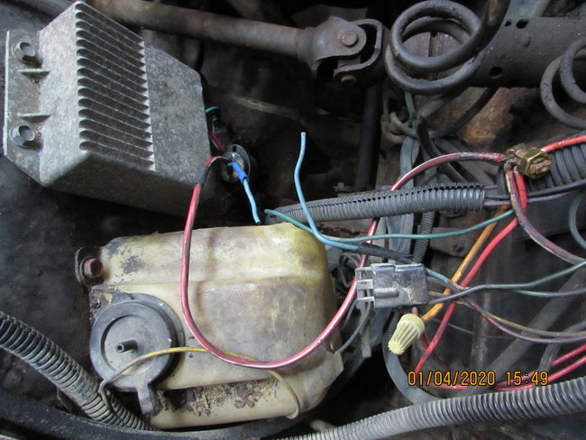
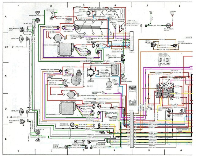
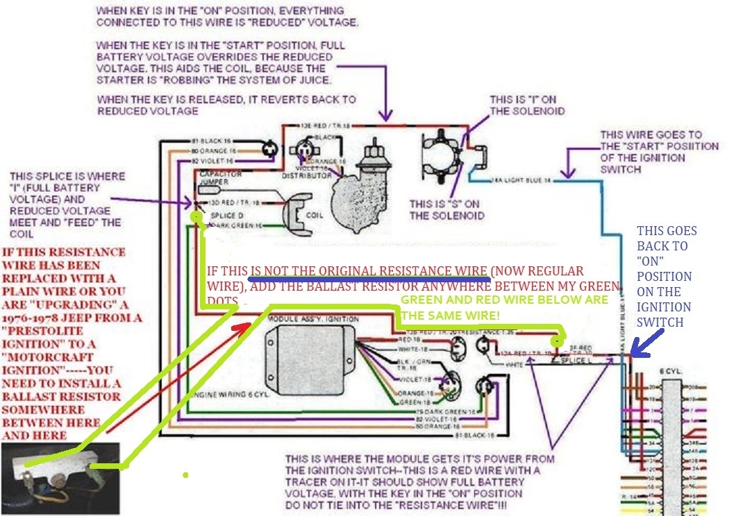
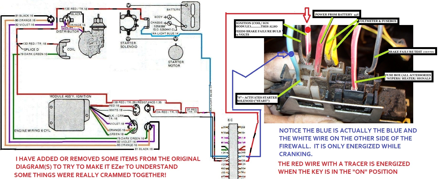
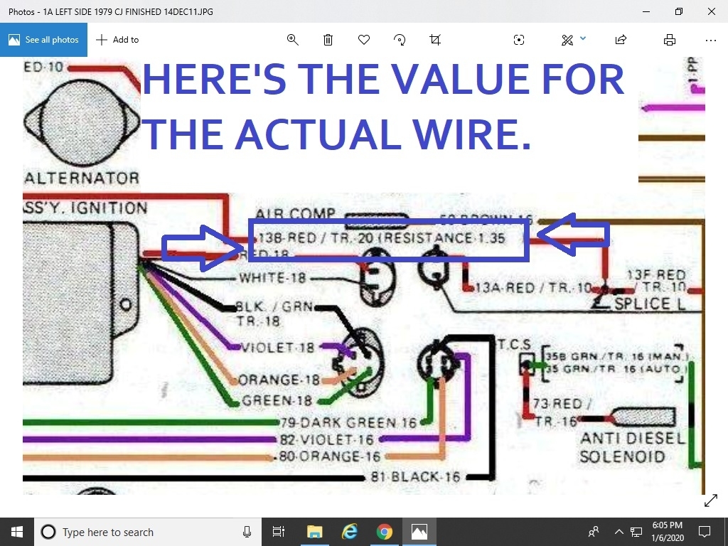
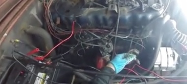
I used the 4th pic to make the 3rd.

I deleted all of the "distractions" to make the 3rd pic.

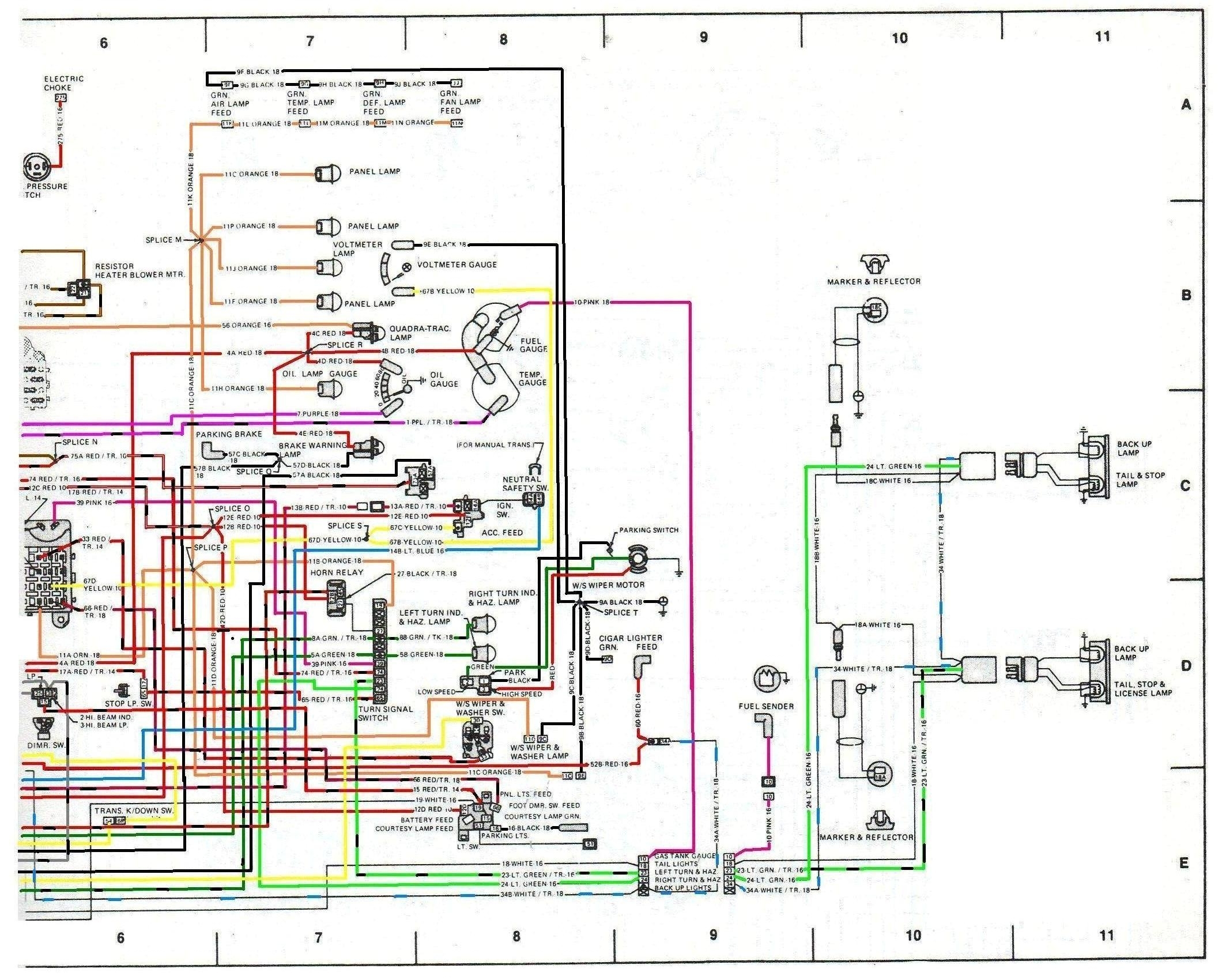
Some places are a little unclear, as so much info is crammed into smaller places. (Like one spot being around "Splice L" )(bottom right).

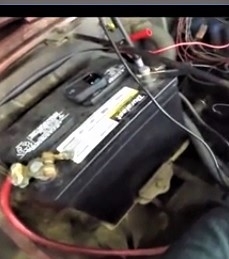
Fuse box is in the 4th pic with another overlap of it in the fifth pic

The rectangle I think you are confusing with the fuse box is "Big Connector" whereas the wiring transitions/ or passes through the firewall into the tub.

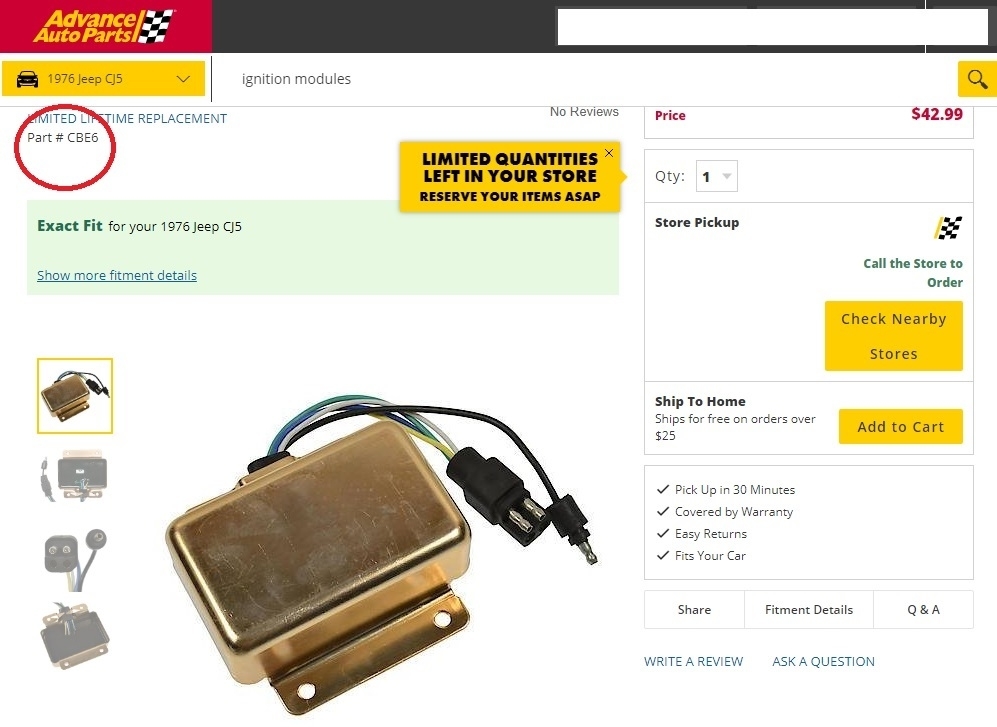
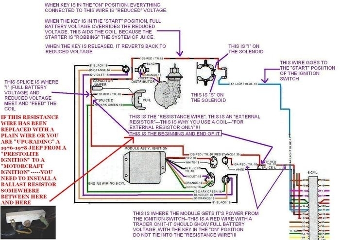
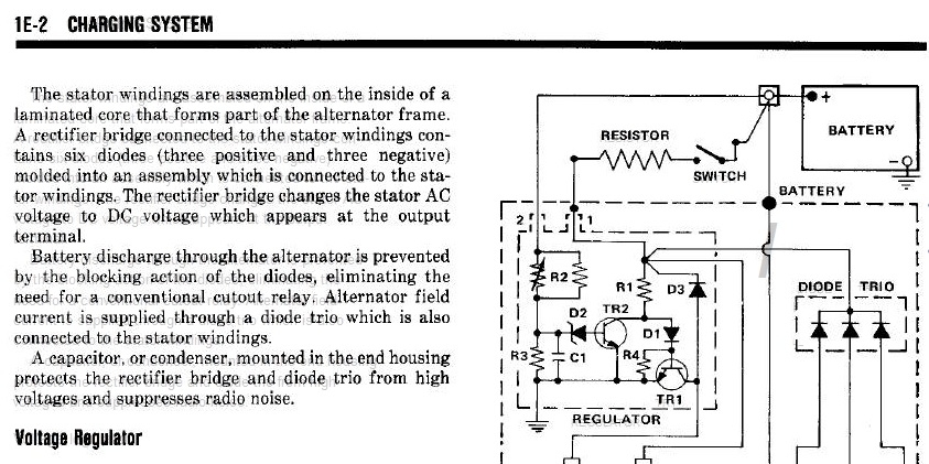
When Motorcraft ignition was introduced so was the "resistance wire".

Before then ('79), That "feed" was a plain ole stranded copper wire, as no resistance was needed to feed Prestolite.

Well, what I have done over time was to try to show people (with my diagrams) how to upgrade from the crappy Prestolite system to the nicer Motorcraft system.

I have it down to being uncomplicated!

Here's what has to be changed:
Distributor
Distributor Cap
Rotor Button
Spark Plug Wires
Spark Plugs
Coil (and it's connector)
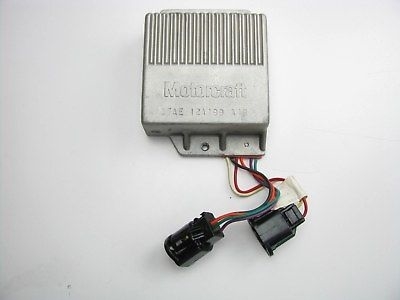
Ignition Module (and its connections)
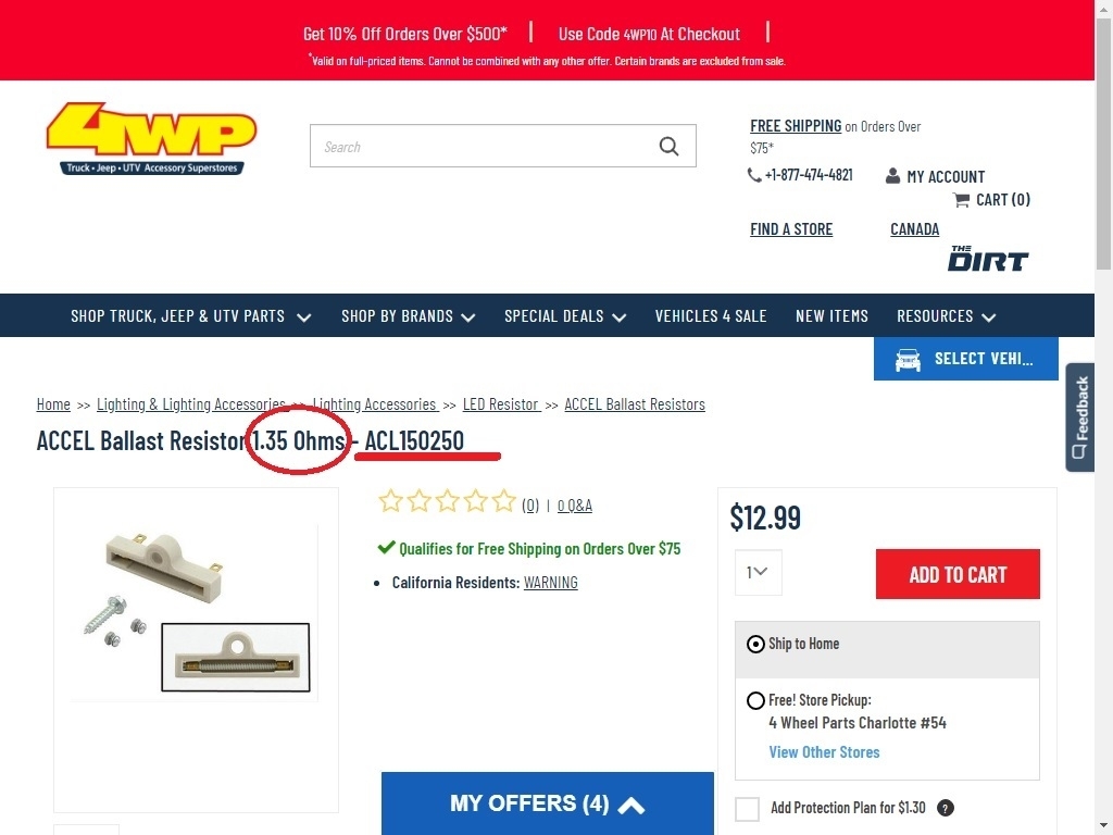
***Ballast resistor
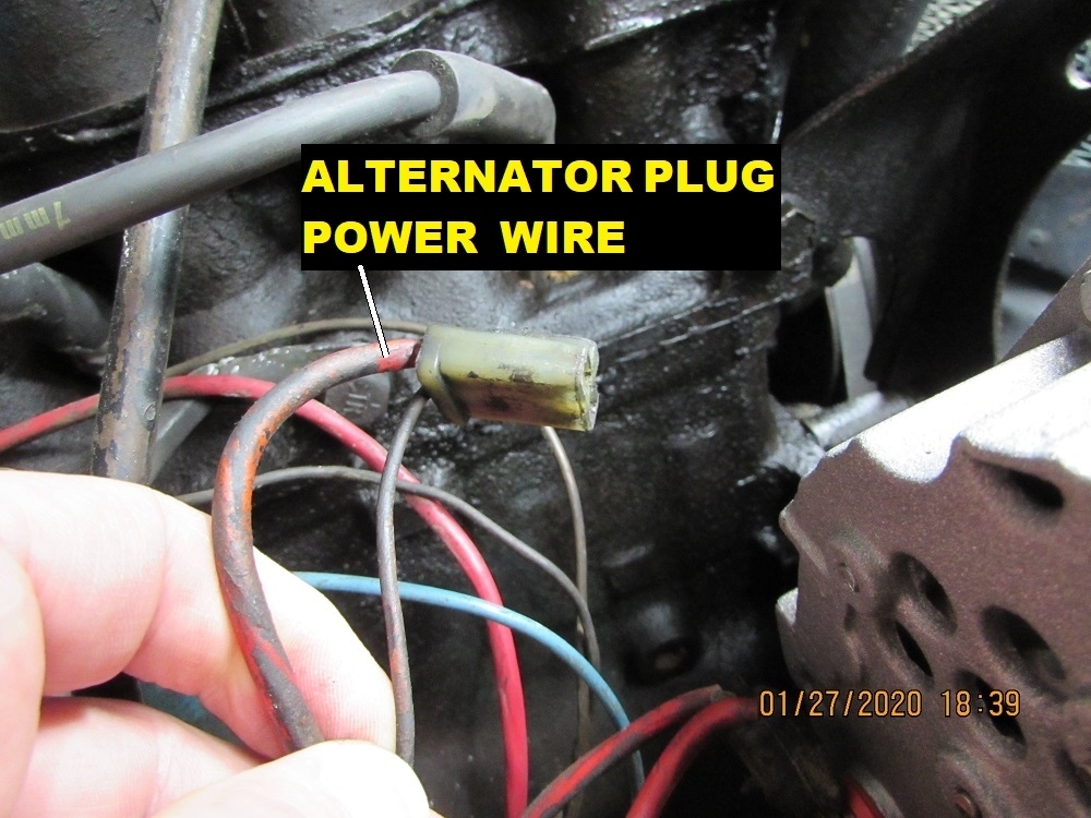
Find where and tie onto the old systems power.

When the upgrade is finished, one (with a '76 or '77) Can simply go into an auto parts store and tell them they have a 1979 and request any part as if they originally had a 1979 with Motorcraft!

I hate seeing things thrown together using anything that "will/ might work" with no sympathy for themselves or anybody else that may need to maintain or troubleshoot the Jeep on down the road!

The only upgrade part that is "Funky" is the "Ballast Resistor" (which is the easiest way I could substitute for the "non-existent" resistance wire in the earlier CJ)

Another way to put it:

Ballast resistor = resistance wire (but you cannot have both at the same time!)

Maybe it's making sense now?

I have many many diagram variations (like hundreds) I have made. I'm presently looking for the one showing the "tie in points" from the Prestolite Jeeps. Those diagrams are originally crudely factory drawn.

I just remade this one for you, better?

I know you have heard of "Nutter Bypass", that's the "fix" for problems that the later year CJs had. The computer was an addition in 1981.
Ignition wires ran through it and were controlled by it.

In a nutshell, wiring one of those later Jeep's ignition wiring to be hooked up like the '79 diagram I'm showing you is the Nutter! (They have a resistance wire- no need for the ballast resistor)

The Medic
Was this
answer
helpful?
Yes
No
+1
Saturday, January 4th, 2020 AT 10:30 PM
Tiny
FANTASTECH
  • MEMBER
  • 10 POSTS
Thank you. It sounds like all I need is the Ballast resistor.

So is this right: IG. “ON” to IG. Box to Ballast (+) to coil (+). Also *I terminal* to ballast (-), bypassing the ballast during cranking.

If the fuse box is not part of the route, are there no fuses protecting these components?
Was this
answer
helpful?
Yes
No
Sunday, January 5th, 2020 AT 7:37 AM
Tiny
CJ MEDEVAC
  • MECHANIC
  • 11,004 POSTS
Fuses and fusible links show elsewhere!

Spent a few hours trying to improve the "Power" needed for the Motorcraft system.

I hope that the right side of the diagram tells exactly what must power the 2 wires on the module.

Maybe this could be an explanation that would help "select" the needed "tie ins" even if the wiring is run differently (different pathways)

Does it aid you at all?

"I" terminal really does not bypass the ballast resistor, it simply "overrides" or "overpowers" it during "cranking".

The Medic
Was this
answer
helpful?
Yes
No
Sunday, January 5th, 2020 AT 1:55 PM
Tiny
FANTASTECH
  • MEMBER
  • 10 POSTS
Thank you for the all the effort you put into your responses. I'm ordering a ballast resistor and I'll work on fixing wires while I'm waiting. I'll report back after I hook it up.
Was this
answer
helpful?
Yes
No
Sunday, January 5th, 2020 AT 2:11 PM
Tiny
FANTASTECH
  • MEMBER
  • 10 POSTS
Do you know how many ohms the ballast should have? My coil is about 1.4 ohms and it seems the Ballast should be between 1.3 and 1.5 - evidently they can fluctuate but the total resistance needs to be about 3 ohms for a 12v system. Yet some of the Ballast resistors that are recommended for my Jeep have 5 or 6 ohms.
Was this
answer
helpful?
Yes
No
Monday, January 6th, 2020 AT 2:21 PM
Tiny
CJ MEDEVAC
  • MECHANIC
  • 11,004 POSTS
Make it as perfect as possible?

See my last two masterpieces.

The Medic
Was this
answer
helpful?
Yes
No
Monday, January 6th, 2020 AT 4:30 PM
Tiny
FANTASTECH
  • MEMBER
  • 10 POSTS
Thank you. Here's my current issue (possibly still related): With my (-) battery cable disconnected and my (+) connected, I began checking for voltage with my DMM. I have 12v on the engine. When I disconnect the hot wire from the 2 terminal of my alternator, it's gone. Thinking my alternator diodes were bad, I tried a new alternator and found the same. Thinking the alternator plug is bad, I bypassed it with a jumper wire and I still have the voltage on the oil cap. Maybe the alternator output wire is supposed the have a diode, but I see nothing about it in the manual or on internet forums, etc. Do you know what the problem is? Thank you, 2CarPros.
Was this
answer
helpful?
Yes
No
Monday, January 27th, 2020 AT 2:11 PM
Tiny
CJ MEDEVAC
  • MECHANIC
  • 11,004 POSTS
You have lost me with this testing!

Remove the alternator, have it tested at the parts store.

Oil cap has voltage?

The Medic
Was this
answer
helpful?
Yes
No
Monday, January 27th, 2020 AT 8:00 PM
Tiny
FANTASTECH
  • MEMBER
  • 10 POSTS
Parts store says the alternator is good. Yes, I have voltage on the engine when the alternator is plugged in. DMM negative lead on the battery (-) and positive lead on the oil cap and I have 12v. I've attached a video.
Was this
answer
helpful?
Yes
No
Tuesday, January 28th, 2020 AT 11:00 AM
Tiny
FANTASTECH
  • MEMBER
  • 10 POSTS
I'm thinking it is supposed to be that way. According to the manual: "The No. 2 terminal on the alternator is always connected to the battery, but the discharge current is limited to a negligible value by the high resistances of the [resistors] R2 and R3."
Can you confirm that your jeep has 12v on the oil cap (or somewhere on the engine) when not running? It's all because there is continuity b/w terminal 2 and the alternator housing.
Was this
answer
helpful?
Yes
No
Tuesday, January 28th, 2020 AT 2:19 PM
Tiny
CJ MEDEVAC
  • MECHANIC
  • 11,004 POSTS
I need better information as to how you are testing from what to what what is disconnected?

The video was nice to see, still vague as to the connections.

Tell me what the other stuff is.

I made several screenshots and blew them up- still can't make out what I need to see.

The Medic
Was this
answer
helpful?
Yes
No
Tuesday, January 28th, 2020 AT 3:27 PM

Please login or register to post a reply.

Sponsored links