Good evening,
The idle air control is part of the throttle body and is not replaceable without replacing the throttle body itself.
https://www.2carpros.com/articles/engine-surges
Roy
Throttle Actuator Control (TAC) System Description
The throttle actuator control (TAC) system is used to improve emissions, fuel economy, and driveability. The TAC system eliminates the mechanical link between the accelerator pedal and throttle plate as well as replaces the need for a cruise control module and idle air control motor. The TAC system components include:
Important: The APP sensors may be serviced separately from the pedal/bracket assembly.
- The accelerator pedal assembly -- This contains the accelerator pedal, accelerator pedal position (APP) sensor 1, and APP sensor 2.
- The throttle body assembly -- This contains the TP sensor 1, TP sensor 2, throttle actuator motor, and throttle plate.
- The engine control module (ECM)
The engine control module (ECM) reads the driver's demand for acceleration through 2 APP sensors. APP sensor 1 signal voltage is scaled from 0.40-3.82 volts (2002), 0.98-3.68 volts (2003 and later), as the accelerator pedal is moved from the rest to full travel position. APP sensor 2, however, is scaled from 0.22-1.92 volts (2002), 0.49-1.84 volts (2003 and later), in the same fashion. The ECM processes this information along with other sensor inputs to command the throttle plate to a certain position.
The throttle plate is controlled with a direct current motor called a throttle actuator control motor. The ECM can move this motor in the forward or reverse direction by controlling battery voltage and/or ground to 4 internal drivers. The throttle plate is held at a 7 percent rest position to a mechanical stop by a constant force return spring. This spring will hold the throttle plate to the stop when there is no current flowing to the actuator motor. There is another return spring, which creates constant force on the throttle plate only when the throttle plate is moved towards the full closed position.
The ECM reads the throttle plate angle through 2 TP sensors. TP sensor 1 signal voltage is scaled from 0.50-4.25 volts as the throttle plate is moved from 0 percent to wide open throttle. TP sensor 2, however, decreases from 4.45-0.70 volts as the throttle plate is moved from 0 percent to wide open throttle.
The ECM performs diagnostics that monitor the voltage levels of both APP sensors, both TP sensors, and the throttle actuator control motor circuit. It also monitors the spring return rate of both return springs that are housed internal to the throttle body assembly. These diagnostics are performed at different times based on whether the engine is running/not running or whether the ECM is currently in a throttle body relearn procedure.
Important: Under cold conditions, the ECM will command the throttle plate to 14 percent with the ignition ON and the engine OFF to prevent ice from building up on the throttle plate.
At every key-up, the ECM will run a quick throttle return spring check to make sure the throttle plate can return to the 7 percent rest position from the 0 percent position. This is to ensure that the throttle plate can be brought to the rest position in case of an actuator motor circuit failure.
Throttle Body Relearn Procedure: The ECM stores values that include the lowest possible TP sensor positions, 0 percent, the rest positions, 7 percent, and the return rate of both springs. These values will only be erased or overwritten if the ECM is reprogrammed or if a throttle body relearn procedure has been performed.
Important: If the battery is disconnected, the ECM will immediately perform a throttle body relearn procedure upon key-up.
A throttle body relearn procedure will be performed anytime the ignition is turned ON with the engine OFF for longer than 29 seconds when the following conditions have been met:
- The engine speed is less than 250 RPM.
- The vehicle speed equals 0 mph.
- The ECT is between 5-100°C (41-212°F).
- The IAT is greater than 5°C (41°F).
- The accelerator pedal angle is less than 15 percent.
- The battery voltage is greater than 10 volts.
After 29 seconds, the ECM will move the throttle plate from the rest position to full closed, then to around 10 percent open. This will take about 2-3 seconds. If any faults occur in the TAC system, a DTC will be set. At the start of this procedure, the scan tool TAC LEARN COUNTER parameter should display 0, then count up to 9 or 11 after the procedure has been completed. If the counter did not start at 0, or if the counter did not end at 9 or 11, a fault has occurred and a DTC should be set.
TAC SYSTEM DEFAULT ACTIONS/LIMP HOME MODES: There are 2 limp home modes that the ECM can default to if an error is detected in the TAC system. If an APP sensor 1 or sensor 2 circuit fault is detected, the ECM will go into 1 of the 2 limp home modes. In this mode, the maximum accelerator pedal angle value is set to 10 percent and a rate at which the rise in pedal angle is severely slowed. The ECM will remain in this limp home mode during the entire ignition cycle even if the fault is corrected.
If a throttle actuator circuit fault, throttle actuator command vs. actual position fault, return spring check fault or a TP sensor 1 circuit fault, below 80 km/h (50 mph) with no accelerator pedal angle, occurs, the ECM will go into the other limp home mode. In this mode, the engine speed is limited to 1,800 RPM and the #3-#6 fuel injectors are randomly turned OFF. At this time the REDUCED POWER telltale will be commanded ON. The ECM will remain in this limp home mode during the entire ignition cycle even if the fault is corrected.
Throttle body
TOOLS REQUIRED
^ J-43914 Hose Clamp Pliers
REMOVAL
imageOpen In New TabZoom/Print
1. Disconnect negative battery cable.
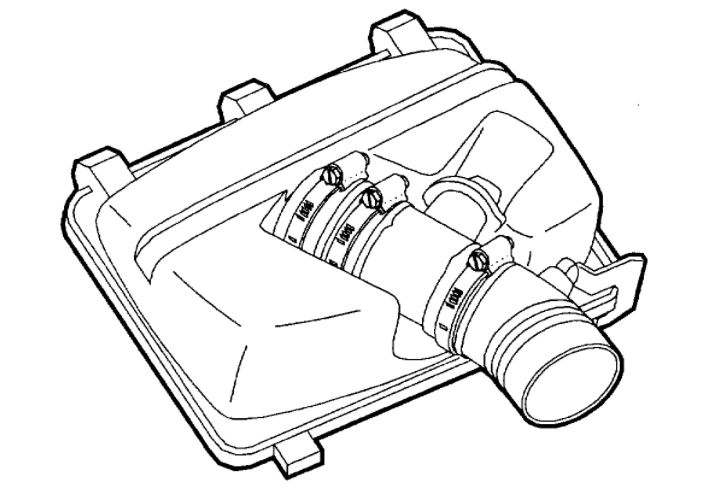
2. Remove inlet hose assembly from throttle body.
3. Disconnect throttle body electrical connection.
4. Disconnect hose clamps from plenum-to-runner connector using J-43914 hose clamp pliers.
imageOpen In New TabZoom/Print
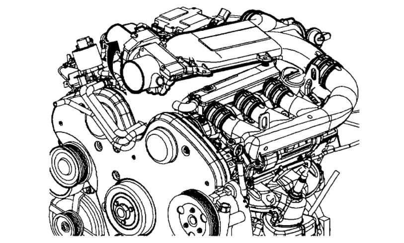
5. Remove intake plenum bolts.
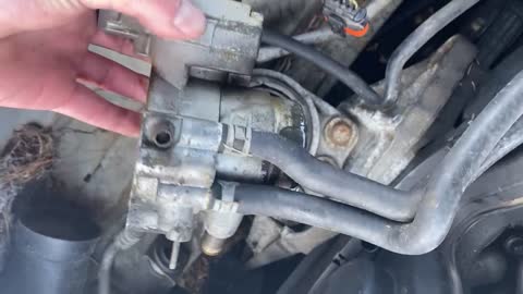
6. Rotate plenum up and remove throttle body coolant hoses, EVAP hose, and vacuum line from throttle body.
imageOpen In New TabZoom/Print
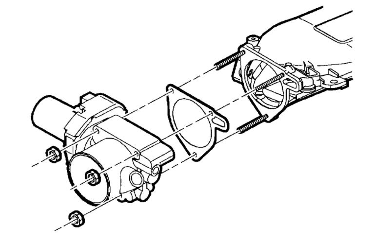
7. Remove throttle body nuts.
8. Remove throttle body.
Installation
1. Install throttle body and new gasket.
2. Install throttle body nut.
Torque: 8 N.m (71 in-lbs)
3. Attach vacuum lines, EVAP hose and coolant lines to throttle body.
imageOpen In New TabZoom/Print
4. Install intake plenum bolts.
Torque: 8 N.m (71 in-lbs)
imageOpen In New TabZoom/Print
5. Connect intake plenum-to-runner hose clamps using J-43914. If clamps are damaged, replace with service screw type clamps.
6. Connect throttle body electrical connector.
imageOpen In New TabZoom/Print
7. Install air cleaner inlet hose.
8. Connect negative battery cable.
Images (Click to enlarge)
Jan 27, 2021 at 6:29 PM