Hello,
Have you carried out a CAN scan to see if there are any relevant fault codes set in relation to your transmission problem?
Suggest connecting a suitable diagnostic tool such as Opcom to check for any relevant fault codes.
How to carry out a CAN scan:
https://www.2carpros.com/articles/can-scan-controller-area-network-easy
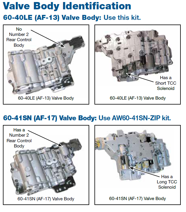
The vehicle is equipped with the AISAN AF17 4 speed automatic transmission
It is very similar to the AF13 transmission with the valve body having a few, small differences.
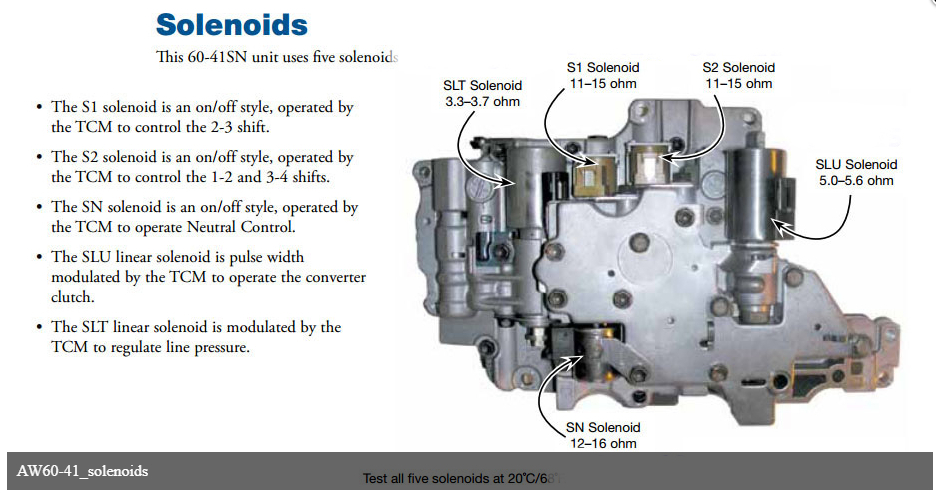
The valve body is the 60-41SN, please see image 1+6
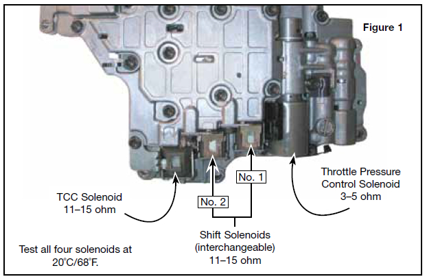
To check shift and pressure solenoids use a voltmeter and check resistance of all five solenoids at 20 degrees C,
The S1 (shift solenoid no. 1) and S2 (shift
solenoid no. 2) are an on/off style, operated by
the TCM to control the various shifts. These two
solenoids are interchangeable.
The TCC control solenoid, SLU, is an on/off style
controlled by the TCM to operate the converter
clutch.
The throttle pressure control liner solenoid, SLT, is
modulated by the TCM to regulate line pressure.
The neutral position solenoid, SN, is operated by the TCM for neutral position
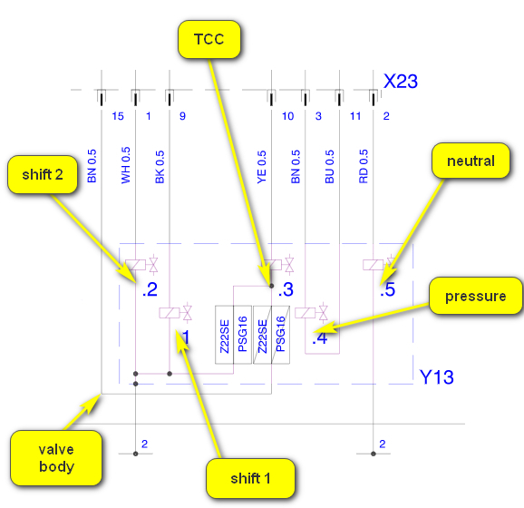
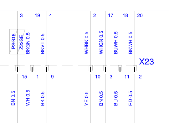
The valve body has no separate voltage supply apart from the control voltage from the TCM to activate individual solenoids. The TCM uses 7 wires via connector X23 to control the valve body solenoids. I have shared with you supply fuse for TCM in my previous reply.
See image 3, shows wiring from connector X23 to valve body.
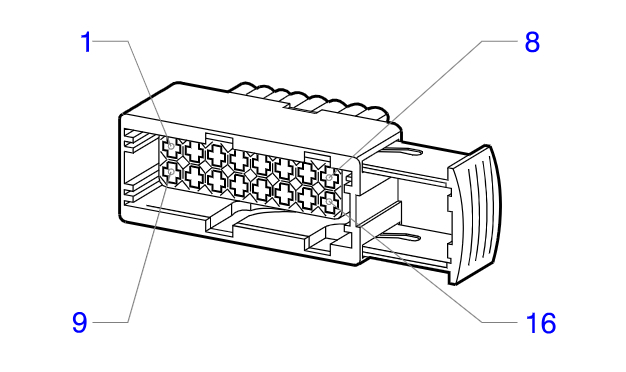
Connector X23 is a 16 pin grey/brown connector on the transmission housing, image 4
Image 5 shows the wiring from the TCM connector to connector X23
To access the valve body will require transmission removal and partial strip down.
Suggest to check the solenoid resistance external at connector X23 using the pin data supplied and using the transmission casing as a ground. All solenoids apart from SLT can be checked this way
Pin 9, black wire to shift solenoid 1(S1) 11-15 ohm
Pin 1, white wire to shift solenoid 2(S2) 11-15 ohm
Pin 3, yellow wire to TCC(SLU) solenoid 5-5.6 ohm
Pin 3, brown wire to pressure solenoid(SLT) back to pin 11, blue wire 3.3-3.7 ohm
Pin 2, red wire to neutral solenoid(SN) 12-16 ohm
These checks can be done using a voltmeter.
How to use:
https://www.2carpros.com/articles/how-to-use-a-voltmeter
Good links for exploded views of valve body and transmission:
https://at-manuals.com/wp-content/uploads/2016/manuals/AW60-40LE-manual.pdf
and
https://at-manuals.com/wp-content/uploads/2016/manuals/60-40LE%2042LE%2041SN%20AF13%20catalog.pdf
Hope this helps.
Cheers, Boris
Images (Click to enlarge)
Aug 28, 2023 at 12:34 AM