Hello .. thanks for the donation .. much appreciated
TIMING & COUNTERBALANCE SHAFT BELTS
Removal
CAUTION:DO NOT rotate engine counterclockwise (as viewed from timing belt end of engine). If reusing timing belt, place reference mark on timing belt to indicate direction of rotation before removing.
Remove drive belts and drive pulleys from crankshaft and water pump. Remove timing belt covers. To align timing marks, rotate engine clockwise so No. 1 cylinder is at TDC of compression stroke. Ensure camshaft sprocket timing marks align with upper surface of rocker cover. Dowel pin of camshaft sprocket should be pointing upward. See Fig. 1 and Fig. 2 .
Remove timing belt auto tensioner. If reusing timing belt, place mark on timing belt to indicate direction of belt rotation. Remove timing belt. Remove camshaft sprockets.
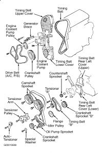
Remove plug at left side of block and insert a screwdriver to hold left counterbalance shaft in position. Screwdriver will have to be inserted at least 2.36" (60 mm). Remove oil pump sprocket nut and sprocket. See Fig. 2.
Loosen right counterbalance shaft sprocket mounting bolt. Remove tensioner "B" and timing belt "B". See Fig. 2. Remove crankshaft sprocket "B" from crankshaft.
Fig. 1: Identifying Timing Belt Alignment Marks
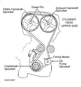
Fig. 2: Exploded View Of Timing Belt & Components
Inspection
Check belt teeth for cracks, damage and oil contamination. Inspect sprockets for damage. Check tensioner pulley and idler pulley for grease leakage and roughness in rotation. Check sprockets and pulleys for wear, cracks or damage. Replace components if necessary.
Measure protrusion of auto tensioner rod. From end of housing, auto tensioner rod should extend .55" (14 mm) on Sonata or .57" (15 mm) on Santa Fe. Replace auto tensioner rod, if not within specification. Place tensioner in a soft-jawed vise, and test resistance of rod. If rod can be easily pushed in with light vise pressure, replace auto tensioner.
Installation
Install crankshaft sprocket "B" onto crankshaft. Ensure flange is properly positioned. Lightly oil outer surface of spacer, and then install spacer onto right counterbalance shaft, with rounded edge of spacer inward.
Install counterbalance shaft sprocket. Tighten flange bolt tightly by hand. Align timing marks on each sprocket and on front case.
When installing timing belt "B", ensure there is no slack in tension side. Install tensioner "B" in center of pulley of left side of mounting bolt, and in pulley flange toward front of engine. See Fig. 3. Align timing mark of right counterbalance shaft sprocket with timing mark on front case.
To tighten timing belt "B", lift tensioner "B" so tension side is pulled tight. Tighten bolt to secure tensioner "B". DO NOT turn shaft, or belt will be over-tightened.
Ensure timing marks are aligned. Ensure center of span on tension side of timing belt "B" can be depressed by hand. Ensure belt deflection is .20-.28" (5-7 mm).
Install crankshaft sprocket flange and sprocket. Ensure flange is mounted in proper direction, with chamfered side toward block. Install special washer and sprocket bolt to crankshaft. Tighten sprocket bolt to specification. See TORQUE SPECIFICATIONS.
Insert long screwdriver through plug hole in left side of cylinder block to hold counterbalance shaft in position. Install oil pump sprocket, and tighten nut to specification. See TORQUE SPECIFICATIONS. Install camshaft sprockets, and tighten bolts. See TORQUE SPECIFICATIONS.
If auto tensioner rod is fully extended, place it in soft-jawed vise, and compress rod slowly until hole in rod lines up with hole in auto tensioner housing. Insert stiff wire to hold rod in this position. Install auto tensioner, leaving wire in place.
CAUTION:If timing marks on camshaft sprockets do not line up properly, DO NOT rotate sprocket more than 2 teeth in either direction, or valve and piston will touch. If necessary to rotate camshaft sprocket more than 2 teeth, rotate crankshaft sprocket counterclockwise first based on the timing mark. After camshaft sprocket is properly timed, return crankshaft to TDC.
Install tensioner pulley onto tensioner arm (on 1999-01 models, pin holes should be in approximately 8 and 10 o'clock positions), and tighten bolt to specification. See TORQUE SPECIFICATIONS. Set timing marks of camshaft sprockets with notches on upper side of rocker cover and dowel pins straight up. Align crankshaft sprocket timing marks. Align oil pump sprocket timing marks.
On 1999-01 models, install timing belt around tensioner pulley and crankshaft sprocket. Secure belt onto tensioner pulley by hand. Pull other side of belt, and install it around oil pump sprocket. Install belt around idler pulley. Install belt around exhaust camshaft sprocket. Turn intake camshaft sprocket one tooth clockwise to align its timing mark with cylinder head top surface. Pull belt with both hands, and install around intake camshaft sprocket. Gently raise tensioner pulley so belt will not sag, and then temporarily tighten center bolt.
On 2002-05 models, align timing mark on each sprocket with the corresponding timing mark, and install the timing belt in the following order: crankshaft sprocket, oil pump sprocket, idler pulley, exhaust camshaft sprocket, intake camshaft sprocket, then tensioner pulley.
On all models, ensure timing mark of each sprocket is still aligned. When checking alignment of oil pump sprocket timing marks, remove plug from hole in left side of cylinder block and insert long screwdriver 2.36" (60 mm) or more to verify that counterbalance shaft is in position. After checking timing mark, reinstall plug using liquid gasket. Remove wire from auto tensioner.
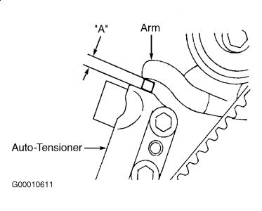
Rotate crankshaft 2 complete turns clockwise. Leave in this position for about 15 minutes. Measure auto tensioner protrusion "A" (distance between tensioner arm and auto tensioner body). Ensure auto tensioner protrusion is .24-.31" (6-8 mm). See Fig. 4. Install timing belt lower cover and upper cover. Note proper location of each bolt. See Fig. 5 or Fig. 6 .
Fig. 3: Installing Tensioner "B"
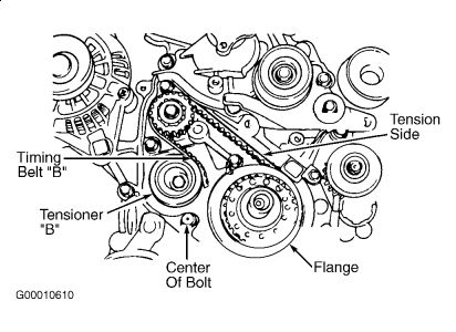
Fig. 4: Measuring Auto Tensioner Protrusion
Hope this helps

Sunday, March 7th, 2010 AT 5:56 AM


