Hi and thanks for using 2CarPros.
The heater core is located under the dash and somewhat hard to access. Here are the directions for replacement. The attached pictures correlate with these directions.
___________________________________________
HEATER CORE
Heater Core
Special tools, testers and auxiliary items required
Hose Clamps, Up to 40 mm (3093) and Hose Clamps Up to 25 mm (3094)
Compressed air gun, commercially available
Cooling System Tester (V.A.G 1274) (and corresponding adapter)
Preliminary Work for Removing
- Protect driver and front passenger seats using seat covers.
- Switch off ignition.
- Dissipate pressure in coolant circuit by opening cap at coolant expansion tank.
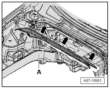
- Remove components which hinder access to coolant hoses to heater core in engine compartment - A - and - B -.
Picture 1
Depending on engine and version of vehicle, it may be necessary to loosen or to remove the following components (top engine cover, pressurized air pipe to throttle valve part and depending on engine the intake manifold, etc.).
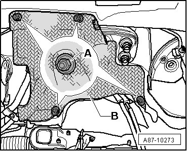
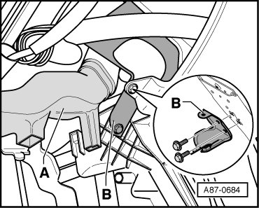
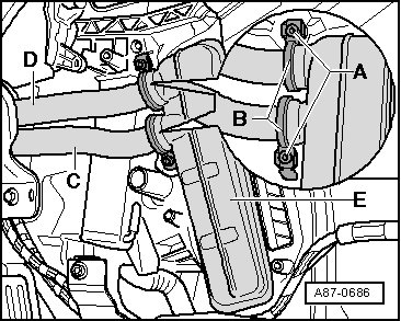
Depending on the engine (for example, on certain 2.0L diesel engine, depending on the exhaust system version), it may be necessary to remove the plenum chamber cover and the plenum chamber front wall - A - in order to remove the head shield, and the refrigerant lines from the expansion valve and the coolant hoses to the heater core.
Picture 2
The heat shield - B - is available in different versions. On version 1, it is not necessary to remove the sheet metal nuts - A - and to disengage the heat shield - B - from the vehicle (coolant hoses may be disconnected even with the heat shield installed).
Picture 3
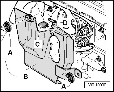
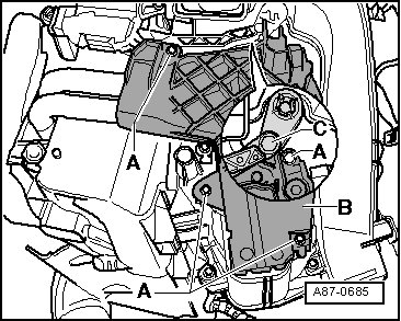
On version 2, it is necessary to remove clamping washers - A - and clamp - C - and to disengage heat shield - B - from vehicle.
Picture 4
For the sake of clarity, the illustrations show the heat shield - B - with the engine removed.
- If present and it becomes necessary, disengage heat shield - B - from front wall of plenum chamber front wall and from the bulkhead and set it aside (or remove it completely).
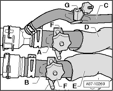
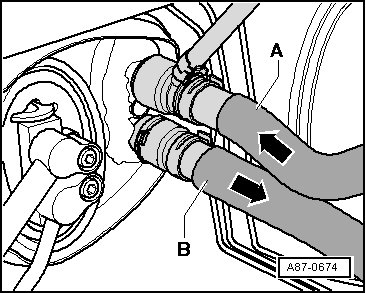
- Slide a thermal protective cover - D - and - E - as far back as possible until it is possible to installed the (3093) - F - onto the coolant hoses - A - and - B -.
Picture 5
- Mark arrangement of coolant hoses - A - and - B -.
Picture 6
The heater core is designed for a specific coolant flow direction, therefore coolant hoses must be connected on the proper sides (coolant hose - A - supply from cylinder head, coolant hose - B - return to coolant pump).
The coolant hose arrangement is the same in both vehicles without and with A/C, this illustration shows a vehicle with A/C.
Bleed the coolant circuit.
- If necessary, clamp off vent hose (from upper connection - A - to coolant expansion tank).
- Cover the area beneath connections for coolant hoses - A - and - B -, for example, with a paper towel.
- Clamp off the coolant hoses to the heater core in the A/C unit (heater) (for example, using (3093) ) and remove the coolant hoses.
- Connect one section of hose - A - on to upper connection.
Picture 7
- Hold a container - B - under the lower connection - C -.
- Using a compressed air gun, carefully blow coolant out of heater core (into container - B -).
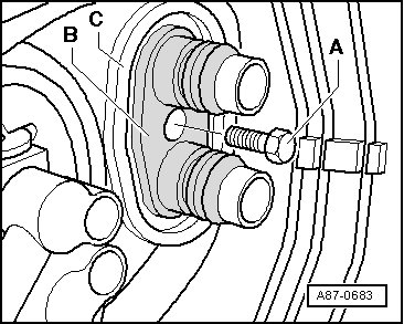
- Remove bolt - A - from connector flange - B - (so that coolant pipes can be moved to remove heater core).
Picture 8
- Remove storage compartment on driver side.
- Remove center console.
- Remove left foot-well vent - A - (driver side).
Picture 9
- Remove the bracket - B -.
- In vehicles with an electric auxiliary heater (only vehicles with Diesel engine), remove Auxiliary Air Heater Heating Element (Z35) (with Auxiliary Air Heater Control Module (J604) ). Refer to=> [ Auxiliary Air Heater Heating Element (Z35) with Control Module (J604) ] See: Auxiliary Cabin Heater > Removal and Replacement > Auxiliary Air Heater Heating Element (Z35) With Control Module (J604).
Removing
- Remove 4 bolts - A - and remove cover - B -.
Picture 10
This illustration depicts the version of A/C unit with electric auxiliary heater.
Cover - B - is different versions (for vehicles without or with electric auxiliary heater).
Picture 11
If lever - C - is located in an unfavorable position so that top bolt - A - is not accessible, switch ignition on and select a different temperature setting (for example, "Hi" setting on Climatronic Control Module (J255) / temperature rotary switch at "Warm" stop setting on A/C Control Module (J301) )
- Cover carpet in area under heat exchanger with waterproof foil and absorbent paper towel.
- Remove bolts - A - and remove clamps - B - from connections of coolant pipes - C - and - D - at heater core - E -.
Picture 12
- Disconnect coolant pipes - C - and - D - from heater core - E - (slide coolant pipes toward bulkhead).
- Pull heater core - E - out of heating and A/C unit.
Installing
Installation is carried out in the reverse order while noting the following:
- Check the heater core seals - A - and - B -.
Picture 13
Seal may curl up on insertion if not correctly bonded on.
Cold air may flow past heater core if seal is damaged or not properly fitted.
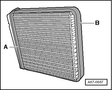
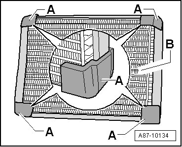
Beginning with MY 2005, the corners of the heater core - B - have an additional foam strip - A -. These foam strips - A - should prevent certain rattling noises which occur especially on vehicles with diesel engines. Attach these strips on all heater cores (for example self-adhesive foam strip with part number 191 819 069. Refer to Electronic Parts Catalog (ETKA)).
Picture 14
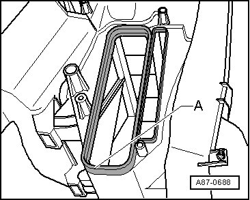
- With the heater core removed, check heating and A/C unit for soiling (via heater core opening - A -).
Picture 15
- Remove any dirt or coolant still inside the A/C unit (heater) after the heater core is removed.
- Slide heater core into heating and A/C unit.
- Remove old clamps - B - from both coolant pipes - C -.
Picture 16
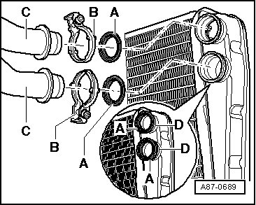
- Install new (included in delivery of heater core) clamps - A - on both coolant pipes for heater core according to illustration.
- Moisten new seals - A - (included in heater core delivery casing) lightly with coolant.
- Insert new seals - A - into connections of heater core - D -.
- Push both coolant pipes - C - into heater core connections - D -.
- Check seating of seals - A - again between coolant pipes - C - and connections of heater core - D -.
- Secure both coolant pipes - C - and - D - with clamps - B - on heater core.
Picture 17
- Tighten bolts on clamps - A - to 2.5 Nm.
- Check seating of both clamps - B - after tightening bolts - A -, clamps must enclose the flange on heater core and coolant pipe completely and must not touch other components.
Picture 18
- Thread bolt - A - into connector flange - B - (while doing this make sure bolt is actually threaded into the mounting point intended for it).
Picture 19
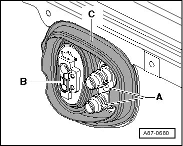
- Check position of grommet - C - in bulkhead for proper seating.
Picture 20
- Seal flange for coolant pipes to heater core - A - and for expansion valve (to evaporator) - B - at pass-through of grommet - C - with silicon adhesive sealant if necessary (to prevent water from penetrating).
- Connect coolant hoses properly to heater core. Observe markings:
Picture 21
A Supply hose from cylinder head
B Return to the coolant pump
- Reinstall all components removed in reverse order, with the exception of cover for connections on heater core and driver side storage compartment.
- Check installation position of coolant hoses to heater cores (they must not contact components which grow hot) and position and state of heat protection insulation applied to coolant hoses if necessary (not installed on all engine types).
- Bleed cooling circuit.
When bleeding coolant circuit, take special care to ensure complete bleeding of heater cores. If there are still air bubbles in the heater core, it may cause the customer to complain of insufficient heating performance in winter or different air temperature from vents at same setting in regulated mode. Refer to => [ Heating Performance Of A/C System, Checking ] See: Heating and Air Conditioning > Component Tests and General Diagnostics > Heating Performance Of A/C System, Checking.
Depending on vehicle equipment and on engine, heat insulation has been applied to coolant hoses, these must not be damaged and must be re-applied after installing.
- Check the cooling system for leaks. Pay close attention to the connections between the coolant pipes and the heater core.
Picture 22
Check the cooling system for leaks:
Bleed coolant circuit.
Carefully open coolant reservoir cap (observe safety cautions when opening the cap).
Increase pressure in coolant circuit, for example, using a hand pump (V.A.G 1274/).
- Reinstall cover for connections on heater core, driver side storage compartment and the remaining components that were removed.
_____________________________________________
Let me know if this is what you needed or if you have other questions.
Take care,
Joe
Images (Click to enlarge)
Feb 3, 2019 at 8:05 PM