Cranks will not start

Tiny
MOORE2127
  • MEMBER
  • 2001 JEEP CHEROKEE
  • 4.0L
  • 6 CYL
  • 4WD
  • AUTOMATIC
  • 175,000 MILES
Got this vehicle the other day and every time I turn the ignition forward to prime the pump it doesn’t prime, so it sits there and cranks but won’t start. Once in a million chances of turning the key back and forth I can sometimes get the pump to prime and when it does it fires right up but will only run for a few seconds. I have had it run for couple minutes but when I go to move it shuts down. Thought It was the pump but I plugged another pump in and still couldn’t get it to prime. I’ve changed the ignition starter switch/ignition lock cylinder also and nothing. What should I do?
Saturday, November 16th, 2019 AT 6:16 PM

19 Replies

Tiny
JACOBANDNICKOLAS
  • MECHANIC
  • 108,188 POSTS
Hi:

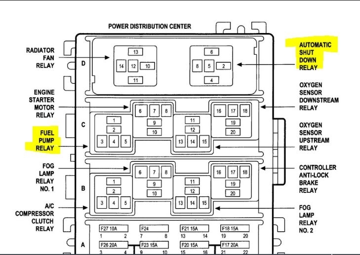
Since you sometimes get power, then I will assume it isn't a fuse. There is an ASD relay (auto shut down) which can shut off the pump and a fuel pump relay. Both are located under the hood in the power distribution box. I attached a pic below showing their locations (Pic1). I would start by checking these circuits and relays. Here are the directions for testing.
____________________________________________________________

2001 Jeep Truck Cherokee 4WD LHD L6-4.0L VIN S
ASD and Fuel Pump Relays Test
Vehicle Powertrain Management Fuel Delivery and Air Induction Fuel Pump Fuel Pump Relay Testing and Inspection Component Tests and General Diagnostics ASD and Fuel Pump Relays Test
ASD AND FUEL PUMP RELAYS TEST
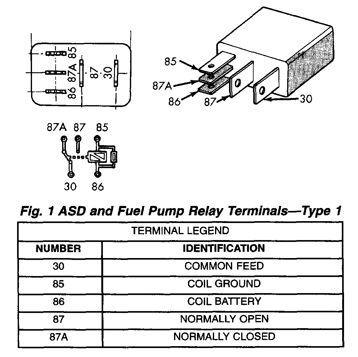
Fig.1 ASD And Fuel Pump Relay Terminals - Type 1

Pic 2

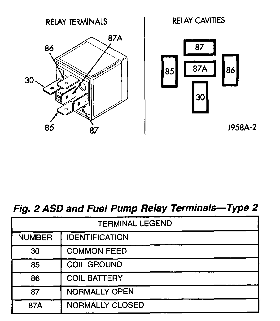
Fig.2 ASD And Fuel Pump Relay Terminals - Type 2

Pic 3

The following description of operation and tests apply only to the Automatic Shutdown (ASD) and fuel pump relays. The terminals on the bottom of each relay are numbered. Two different types of relays may be used, (Fig. 1) or (Fig. 2).
- Terminal number 30 is connected to battery voltage. For both the ASD and fuel pump relays, terminal 30 is connected to battery voltage at all times.
- The PCM grounds the coil side of the relay through terminal number 85.
- Terminal number 86 supplies voltage to the coil side of the relay.
- When the PCM de-energizes the ASD and fuel pump relays, terminal number 87A connects to terminal 30. This is the OFF position. In the OFF position, voltage is not supplied to the rest of the circuit. Terminal 87A is the center terminal on the relay.
- When the PCM energizes the ASD and fuel pump relays, terminal 87 connects to terminal 30. This is the ON position. Terminal 87 supplies voltage to the rest of the circuit.

The following procedure applies to the ASD and fuel pump relays.
1. Remove relay from connector before testing.
2. With the relay removed from the vehicle, use an ohmmeter to check the resistance between terminals 85 and 86. The resistance should be 75 ohms ± 5 ohms.
3. Connect the ohmmeter between terminals 30 and 87A. The ohmmeter should show continuity between terminals 30 and 87A.
4. Connect the ohmmeter between terminals 87 and 30. The ohmmeter should not show continuity at this time.
5. Connect one end of a jumper wire (16 gauge or smaller) to relay terminal 85. Connect the other end of the jumper wire to the ground side of a 12 volt power source.
6. Connect one end of another jumper wire (16 gauge or smaller) to the power side of the 12 volt power source. Do not attach the other end of the jumper wire to the relay at this time.

WARNING: DO NOT ALLOW OHMMETER TO CONTACT TERMINALS 85 OR 86 DURING THIS TEST. DAMAGE TO OHMMETER MAY RESULT.

7. Attach the other end of the jumper wire to relay terminal 86. This activates the relay. The ohmmeter should now show continuity between relay terminals 87 and 30. The ohmmeter should not show continuity between relay terminals 87A and 30.
8. Disconnect jumper wires.
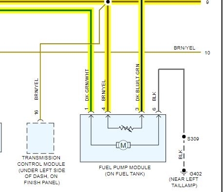
9. Replace the relay if it did not pass the continuity and resistance tests. If the relay passed the tests, it operates properly. Check the remainder of the ASD and fuel pump relay circuits. Refer to Wiring Diagrams.

____________________________________________________________________________-
Was this
answer
helpful?
Yes
No
+1
Sunday, November 17th, 2019 AT 7:29 PM
Tiny
MOORE2127
  • MEMBER
  • 11 POSTS
That’s what I was thinking because I did try a new relay for both fuel pump and auto shutdown and nothing changed. Would the crankshaft position sensor cause the fuel pump not to prime? If I spray starting fluid to fire it up it tries to stay running but dies down and shuts off. The only way I can get it to want to run is when I hear the pump kick on but it doesn’t want to stay running and then after it shuts off I can’t get it to prime so it just sits and cranks but won’t start. I do hear the relays kicking on in the fuse panel under the hood.
Was this
answer
helpful?
Yes
No
Monday, November 18th, 2019 AT 3:51 PM
Tiny
MOORE2127
  • MEMBER
  • 11 POSTS
I will try testing the circuits though for the two relays you listed. Thank you
Was this
answer
helpful?
Yes
No
Monday, November 18th, 2019 AT 3:53 PM
Tiny
JACOBANDNICKOLAS
  • MECHANIC
  • 108,188 POSTS
Let me know what you find.
Was this
answer
helpful?
Yes
No
Monday, November 18th, 2019 AT 5:57 PM
Tiny
MOORE2127
  • MEMBER
  • 11 POSTS
Even If I already changed the relays for the ASD and fuel pump? Cause I did that with new relays and it didn’t change anything.
Was this
answer
helpful?
Yes
No
Monday, November 18th, 2019 AT 7:13 PM
Tiny
JACOBANDNICKOLAS
  • MECHANIC
  • 108,188 POSTS
If it starts starting fluid, then it has spark. The ASD shuts down the fuel pump. Are you sure it isn't an issue with the immobilizer?
Was this
answer
helpful?
Yes
No
Tuesday, November 19th, 2019 AT 5:17 PM
Tiny
MOORE2127
  • MEMBER
  • 11 POSTS
Hard wired the fuel pump to a toggle switch to the battery and fires up and runs now. Not exactly sure what each wire is for what. I tried looking for a diagram of the fuel pump wires but couldn’t find anything. Felt like it’s getting to much fuel now since I ran both grounds together and then both positives of the fuel pump wires. Did it that way just to see if it would run the pump and it did but not sure if I have it wired right.
Was this
answer
helpful?
Yes
No
Tuesday, November 19th, 2019 AT 6:49 PM
Tiny
JACOBANDNICKOLAS
  • MECHANIC
  • 108,188 POSTS
Hi,

At the pump, the wires go to these things:

Dark green/white To fuel pump relay

Dark blue/light green To PCM (low fuel light)

Brown/yellow To camshaft position sensor, O2 sensors, VSS, battery temp
sensor, cruise control

Black To Ground.

I cut a portion of the wiring schematic for you to see. If there is something specific you need, let me know. There are several pages associated with this.

_____________________________________________________

I'm glad to hear it's running. Please keep in mind, the vehicle has an automatic shut down system that turns power off to the pump in the event of a roll over or accident. That will not happen if you have it powered direct.

Let me know if the wiring helps.
Was this
answer
helpful?
Yes
No
Tuesday, November 19th, 2019 AT 7:29 PM
Tiny
MOORE2127
  • MEMBER
  • 11 POSTS
Was wondering what color is which on fuel pump connector?
Was this
answer
helpful?
Yes
No
Wednesday, November 20th, 2019 AT 5:26 AM
Tiny
MOORE2127
  • MEMBER
  • 11 POSTS
I know there is like a 5v and 12v wire for ones priming and the other ones constant. So does that mean I would have to run 2 toggle switches? Or how would I run the switches so its not sending too much fuel?
Was this
answer
helpful?
Yes
No
Wednesday, November 20th, 2019 AT 7:09 AM
Tiny
JACOBANDNICKOLAS
  • MECHANIC
  • 108,188 POSTS
Hi,

I attached a picture of the connector for the pump. It is a 6 pin connector but only 4 are used. I noticed that you have a new connector with different colors. The pic shows what each pin does. Since the wires are different colors, confirm that the pins are in the correct locations. Pins 1, 3, 4, and 6 are the only ones used.
Was this
answer
helpful?
Yes
No
+1
Wednesday, November 20th, 2019 AT 3:02 PM
Tiny
MOORE2127
  • MEMBER
  • 11 POSTS
Thank you. So would putting the (orange and red/black wire together for positive) and the (black and green/black together for ground) and run it to a toggle switch and battery? Am I correct?
Was this
answer
helpful?
Yes
No
Wednesday, November 20th, 2019 AT 3:34 PM
Tiny
JACOBANDNICKOLAS
  • MECHANIC
  • 108,188 POSTS
I would need to determine which color wires on the new plug go to which pin. Look at the pic I attached above, determine the new colors going to the pins, and that should identify which new color should get power and which shouldn't.

Also, please understand that by running a toggle switch, you remove an important safety feature and that is fuel shut off in the event of an accident. Also, it is easy to forget to turn things off.
Was this
answer
helpful?
Yes
No
Wednesday, November 20th, 2019 AT 4:23 PM
Tiny
MOORE2127
  • MEMBER
  • 11 POSTS
Pretty sure red/black and orange are the ones on top like where the red tab is.
Was this
answer
helpful?
Yes
No
Wednesday, November 20th, 2019 AT 4:42 PM
Tiny
JACOBANDNICKOLAS
  • MECHANIC
  • 108,188 POSTS
Hi,

Compare it to the old one and then to the schematic I attached above. I don't want to take a chance and give wrong information causing a short.

Let me know how things work out.
Was this
answer
helpful?
Yes
No
Thursday, November 21st, 2019 AT 1:44 PM
Tiny
MOORE2127
  • MEMBER
  • 11 POSTS
So if the orange and black wire are the 16g wires and the other two would be the 20g which would be used for the fuel sensor guage? And then the 16g would be for the fuel pump? So if that’s right then would I just need the 2 16g wires ran to the battery?
Was this
answer
helpful?
Yes
No
Saturday, November 23rd, 2019 AT 6:20 PM
Tiny
JACOBANDNICKOLAS
  • MECHANIC
  • 108,188 POSTS
Honestly, without being there I can't answer that. Have you tried to compare it to the old plug?
Was this
answer
helpful?
Yes
No
Monday, November 25th, 2019 AT 5:17 PM
Tiny
MOORE2127
  • MEMBER
  • 11 POSTS
Don’t have the old plug to compare too. And also well if the two 20G wires refer to being the fuel gauge sensor and the sensor ground then I wouldn’t need those 20G wires ran in with the 16G correct? Cause I ran the fuel pump relay output wire and the fuel level sensor signal wire together as positive and then the sensor ground wire and ground wire together as the ground and ran it into my battery and switch and it kicks the fuel pump on and fired up but the inline fuse keeps blowing so thinking it’s getting to much power now. Or could I run the fuel level sensor and the sensor ground to the connector and then run the fuel pump relay wire and ground to the battery?
Was this
answer
helpful?
Yes
No
Monday, November 25th, 2019 AT 5:59 PM
Tiny
JACOBANDNICKOLAS
  • MECHANIC
  • 108,188 POSTS
Please understand, my schematics don't offer the wiring gauge. However, the dark green / white wire runs to the relay, so it should be powered. As far as the level sensor, it is most likely the lower power supply you mentioned. The best thing I can suggest is to follow the original layout I gave indicating what each wire does then look at the pin designation and wire those wires to the new plug based on what the pin out shows.

As far as just running power direct, I don't recommend it, but the dark blue /. Light green wire goes to the PCM, so I wouldn't recommend powering that wire. Based on what I am seeing on the schematic, if you supply power to the dark green / white (relay) wire and then ground the black wire, the pump should run.

Please understand, not being there makes me somewhat concerned making these recommendations. I don't want anything to catch fire, melt down, and mostly have you get hurt. I am here to help, I just don't want to have something go wrong for you.

As far as the inline fuse blowing, how many amp fuse are you using? Is the wiring that supplies power to the fuel pump heavy enough to handle the load of the pump? Is the toggle you have capable of the amperage that it will be supplying?

Let me know.

Joe
Was this
answer
helpful?
Yes
No
+1
Monday, November 25th, 2019 AT 7:28 PM

Please login or register to post a reply.

Sponsored links