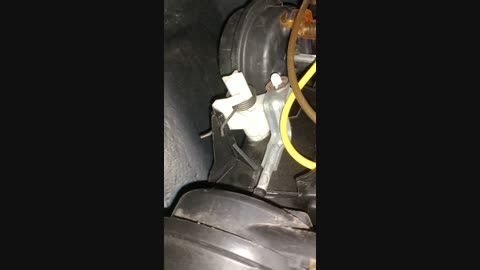
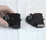
Thanks for the great video. Most likely the shaft has broken and the air door is staying in place. Parts for this specifically are pretty hard to find new. I'd either try eBay or s10forum. Com or swap the entire HVAC box for a used one car-part. Com is a good source to search local salvage yards.
The dash will have to come out to access the HVAC box either way you go. Below is the info on that.
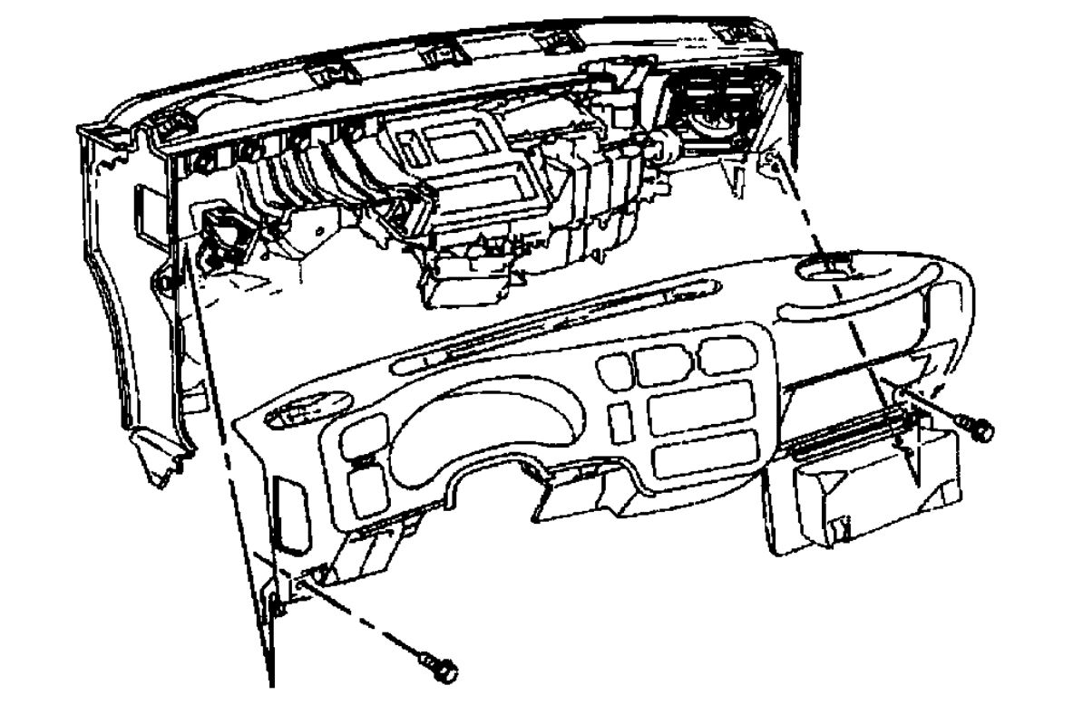
Dash
1. On vehicles equipped with a manual transmission, remove the shift lever.
2. On vehicles equipped with an automatic transmission, perform the following steps:
2.1. Apply the park brake.
2.2. Insert the ignition key and turn the ignition switch to the RUN position.
2.3. Depress the brake pedal and shift the transmission to the 1 position.
2.4. Turn the ignition switch to the OFF position.
CAUTION: Refer to Battery Disconnect Caution in Cautions and Notices.
3. Disconnect the battery negative cable.
4. Remove the left sound insulator.
5. Remove the right instrument panel sound insulator.
6. If the vehicle is equipped with a multiple CD changer located in the center console, remove the center console.
7. Remove the center sound insulator.
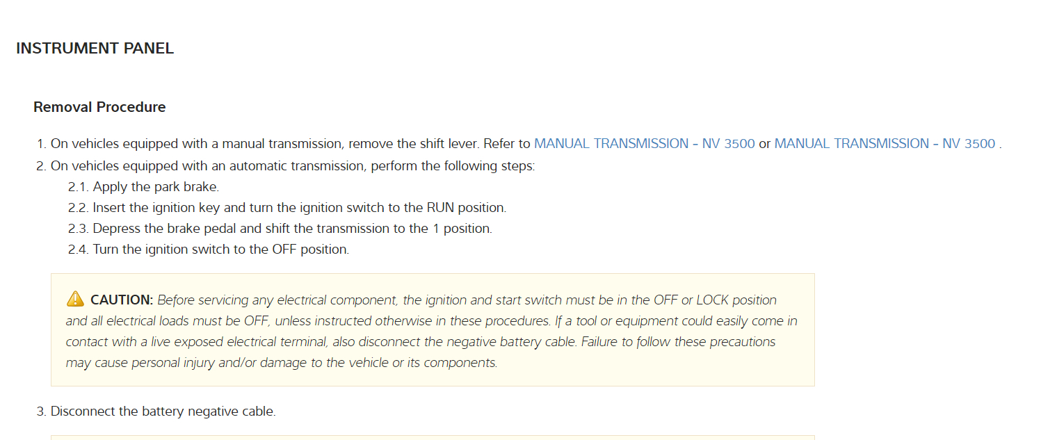
8. Remove the lower left instrument panel mounting bolt.
9. Remove and retain the instrument panel storage compartment.
10. Remove the lower right instrument panel mounting bolt.
11. Remove and retain the left and right speakers and the speaker grilles.
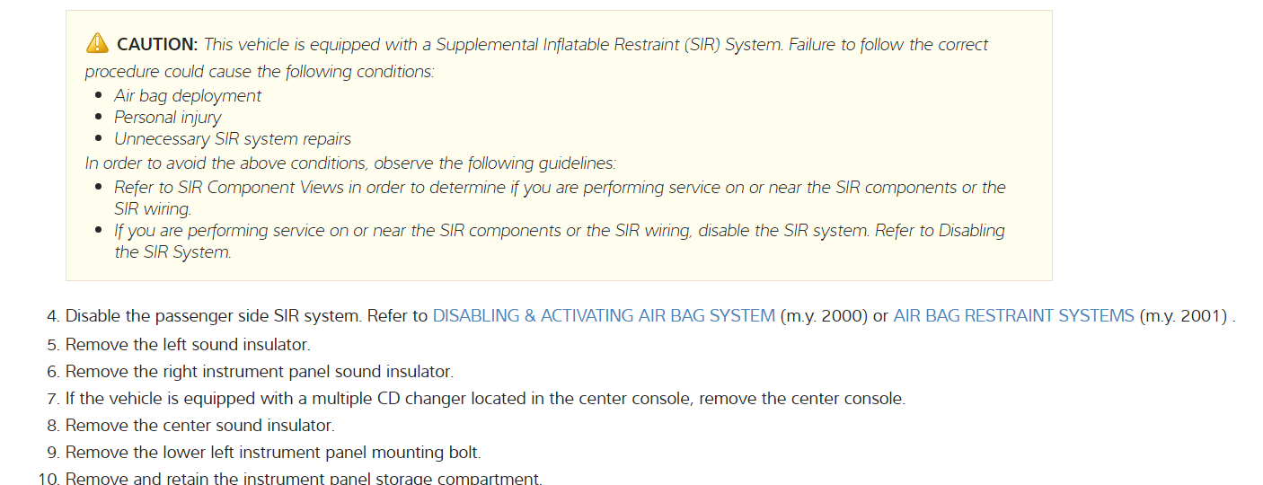
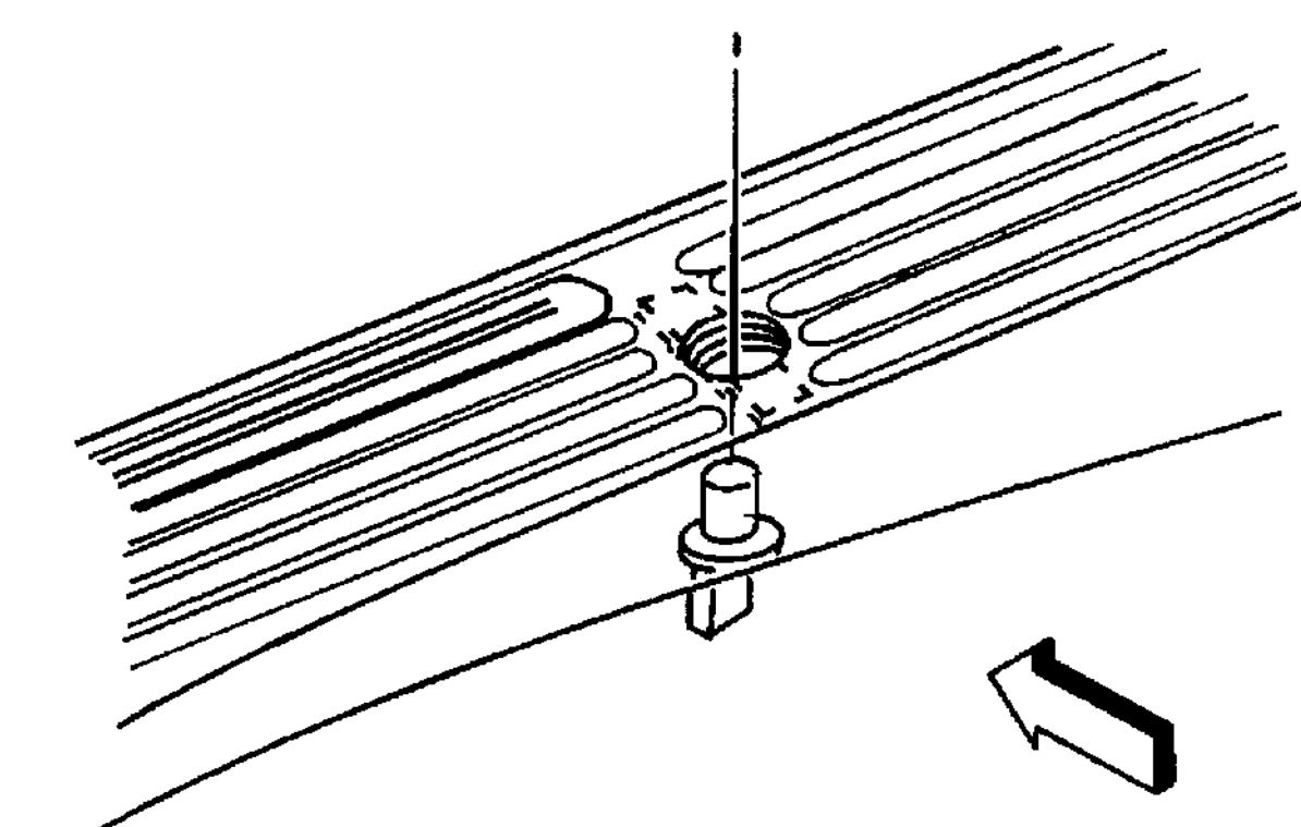
12. Use a flat-bladed tool in order to remove the windshield defroster grille.
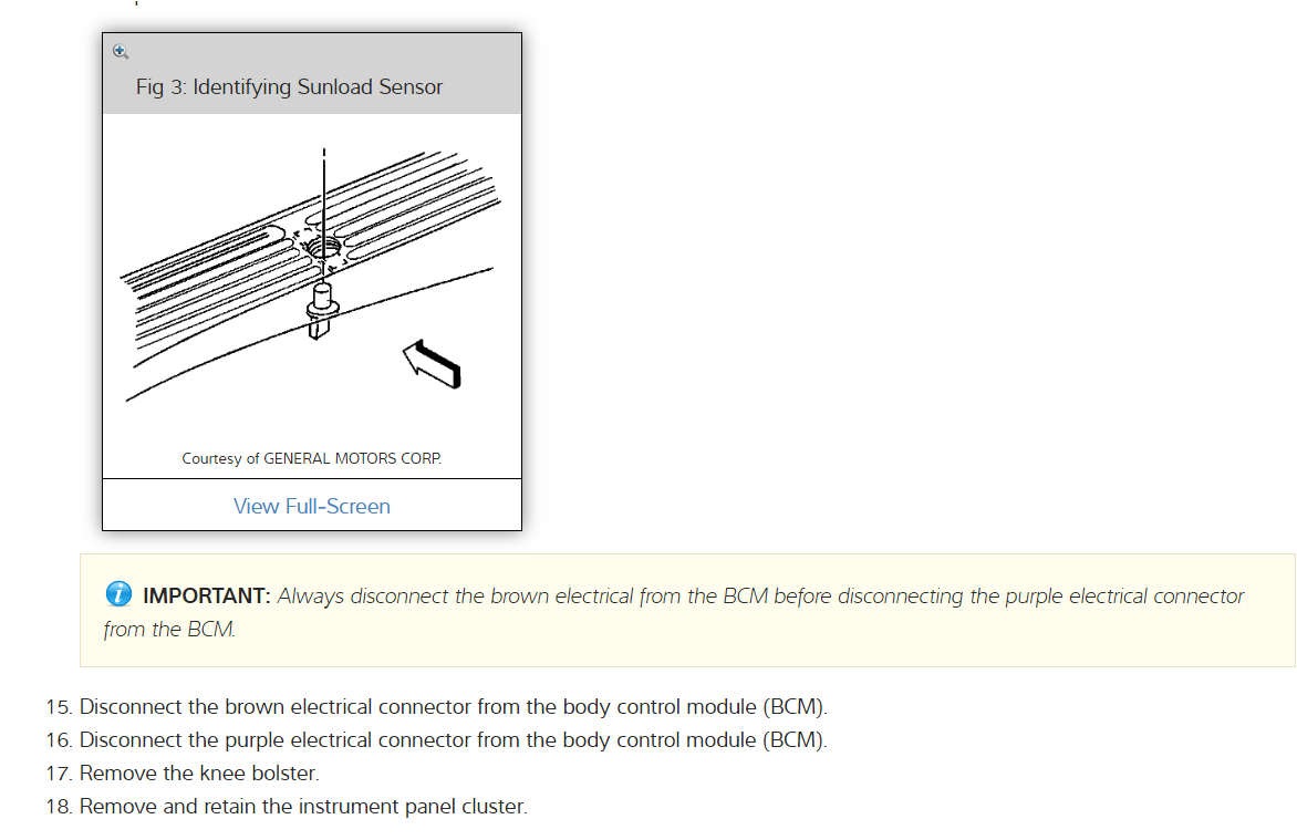
Retain the grille and sunload sensor for use on the next IP carrier.
13. If equipped with a sun load temperature sensor twist the sensor 1/4 turn counterclockwise in order to disengage.
14. Disconnect the brown electrical connection from the body control module (BCM).
15. Disconnect the purple electrical connection from the body control module (BCM).
16. Remove the knee bolster.
17. Remove and retain the instrument cluster.
18. Remove and retain the radio.
19. Remove the HVAC control assembly.
CAUTION: Refer to SIR Handling Caution in Cautions and Notices.
20. Disable the passenger side SIR system.
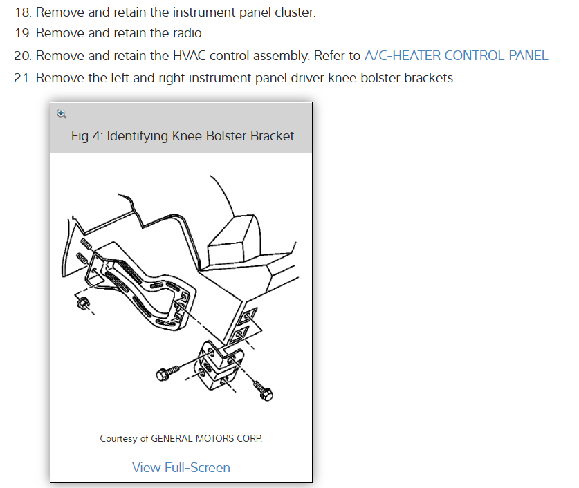
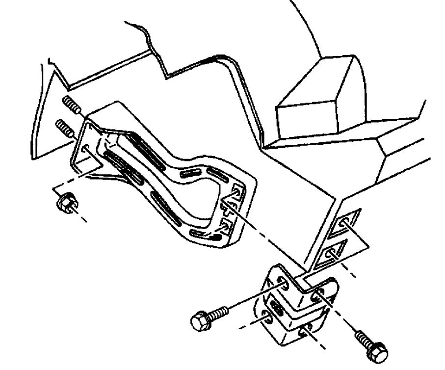
21. Remove the left and right instrument panel driver knee bolster brackets.
22. Lower the steering column for clearance.
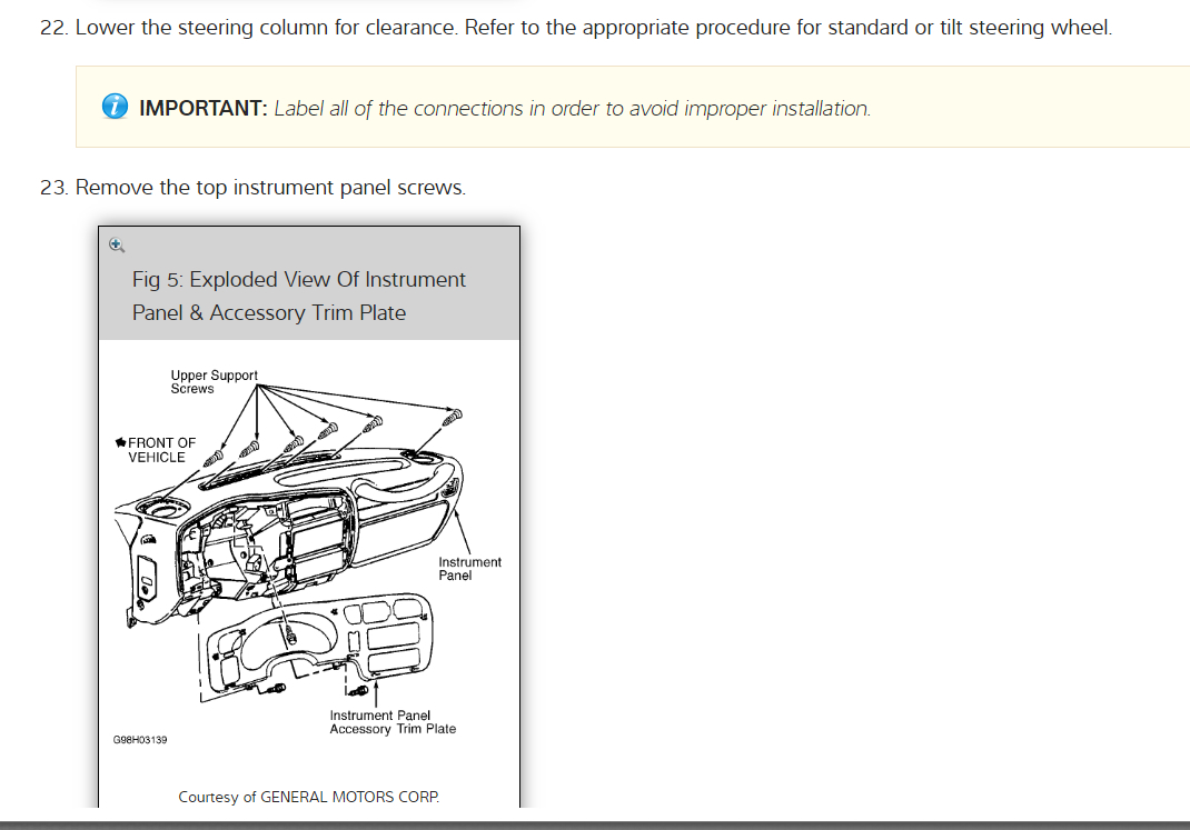
IMPORTANT: Label all of the connections in order to avoid improper installation.
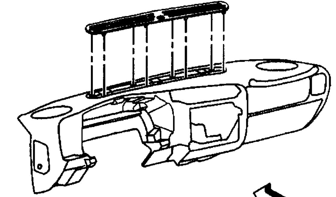
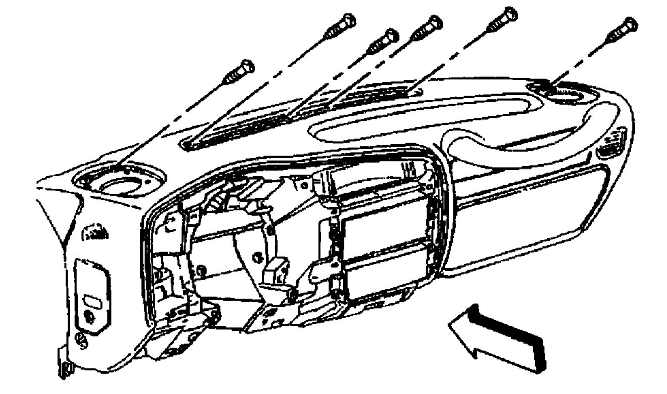
23. Remove the top instrument panel screws.
24. Roll the instrument panel down.
25. Disconnect the electrical connections, as needed.
26. Remove the fastener that retains the radio antenna cable to the instrument panel.
27. Remove the instrument panel from the vehicle. If replacing the instrument panel carrier, retain the parts for assembly of the new instrument panel carrier.
INSTALLATION PROCEDURE
1. Install the retained parts from the original instrument panel.
2. Install the instrument panel to the vehicle.
3. Install the fastener that retains the radio antenna cable to the instrument panel.
Tighten
Tighten the fastener to 1.9 Nm (17 lb in).
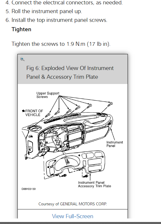
4. Connect the electrical connectors, as needed.
5. Roll the instrument panel up.
6. Install the top instrument panel screws.
Tighten
Tighten the screws to 1.9 Nm (17 lb in).
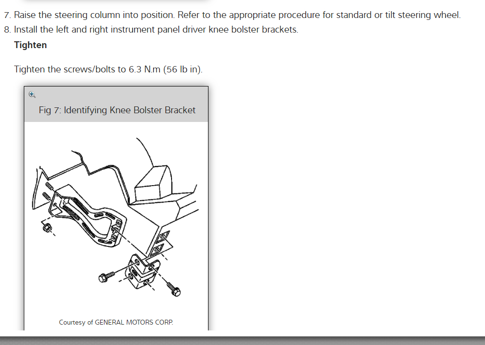
7. Raise the steering column into position.
8. Install the left and right instrument panel driver knee bolster brackets. Tighten the screws/bolts to 6.3 Nm (56 lb in).
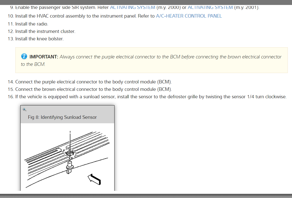
9. Enable the passenger side SIR system.
10. Install the HVAC control assembly to the instrument panel.
11. Install the radio.
12. Install the instrument cluster.
13. Install the knee bolster.
14. Connect the purple electrical connection to the body control module (BCM).
15. Connect the brown electrical connection to the body control module (BCM).
16. If equipped with a sun load temperature sensor, install the sensor to the defroster grille by twisting the sensor 1/4 turn clockwise.
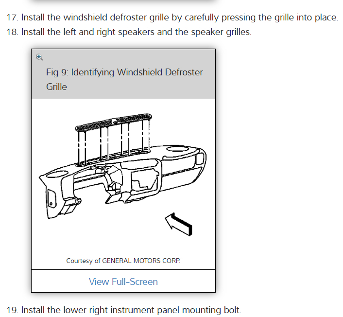
17. Install the windshield defroster grille by pressing carefully pressing the grille into place.
18. Install the left and right speakers and the speaker grilles.
ImageOpen In New TabZoom/Print
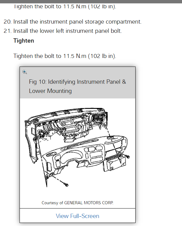
19. Install the lower right instrument panel mounting bolt.
Tighten
Tighten the bolt to 11.5 Nm (102 lb in).
20. Install the instrument panel storage compartment.
21. Install the lower left instrument panel bolt.
Tighten
Tighten the bolt to 11.5 Nm (102 lb in).
22. Install the center sound insulator.
23. Install the right sound insulator.
24. If the center console was removed, install the console to the vehicle.
25. Install the left sound insulator.
26. Connect the battery negative cable.
27. On vehicles equipped with an automatic transmission, perform the following steps:
27.1. Turn the ignition switch to the RUN position.
27.2. Depress the brake pedal and shift the transmission into the PARK position.
27.3. Release the park brake.
28. On vehicles equipped with a manual transmission, install the shift lever.
HVAC BOX
1. Remove the instrument panel. See: Dashboard / Instrument Panel > Procedures
2. Drain the engine coolant.
3. On vehicles with automatic climate control only, cut the outer layer of the A/C evaporator and blower module in order to access the service access cover.
ImageOpen In New TabZoom/Print
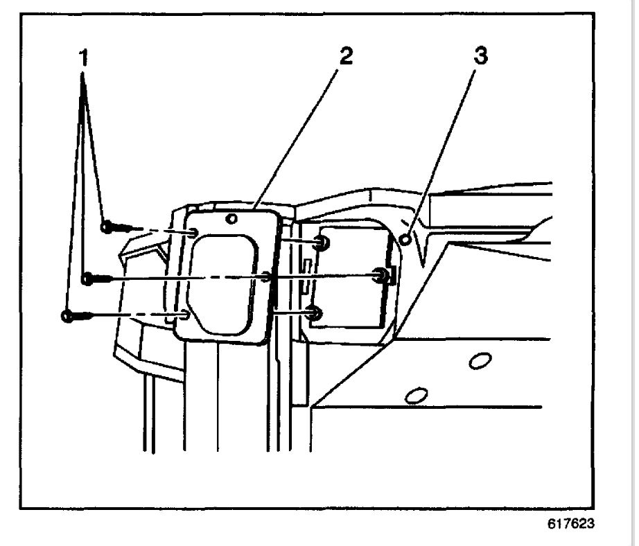
4. On vehicles with automatic climate control only, remove the service access cover mounting screws (1).
5. On vehicles with automatic climate control only, remove the service access cover (2).
6. On vehicles without automatic climate control, remove the blower motor resistor. Refer to Blower Motor Resistor Assembly Replacement (C42) or Blower Motor Resistor Assembly Replacement (C60).
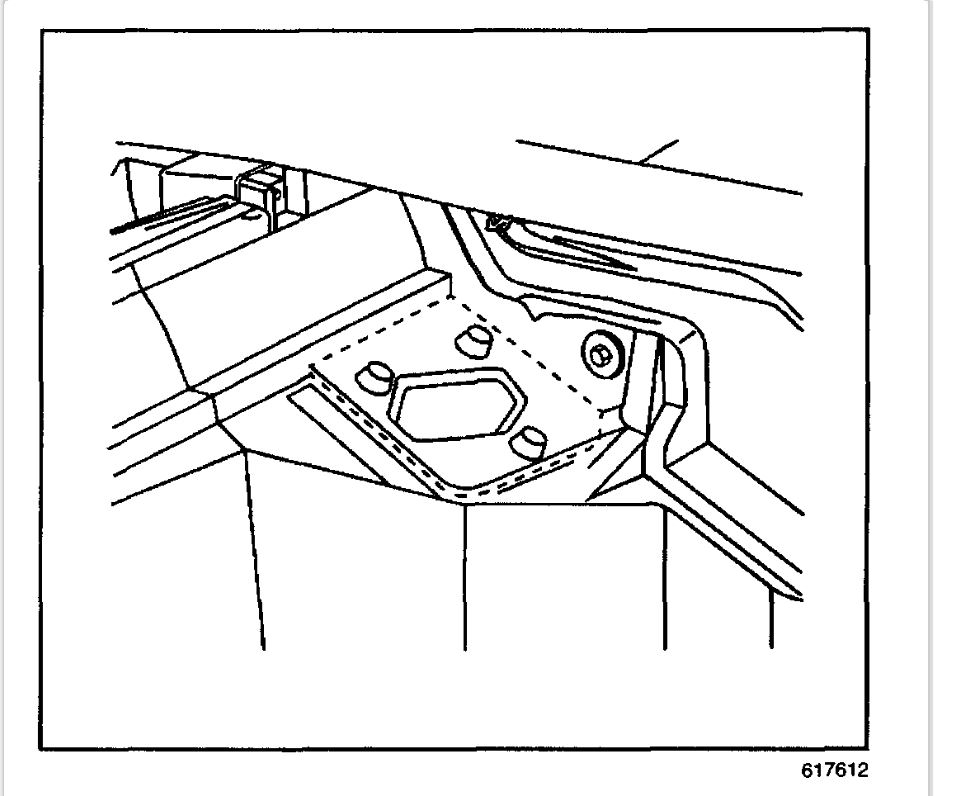
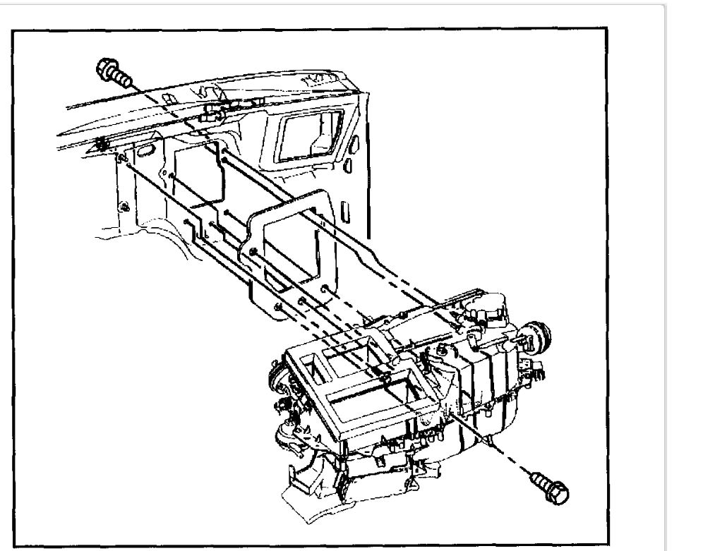
IMPORTANT: Mark and use the same mounting bolt for the heater/vent module during the installation process. Other mounting bolts are longer and will obstruct the operation of the temperature door.
7. Remove the heat/vent module mounting bolt through the blower motor resistor or service access cover opening.
ImageOpen In New TabZoom/Print
8. On vehicles with A/C only, remove the right wheel house panel. Refer to Wheelhouse Panel Replacement in Body Front End.
9. On vehicles with A/C only, raise and support vehicle. Refer to Vehicle Lifting in Maintenance.
10. On vehicles with A/C only, remove the front right tire. Refer to Tire and Wheel Removal and Installation in Tires and Wheels.
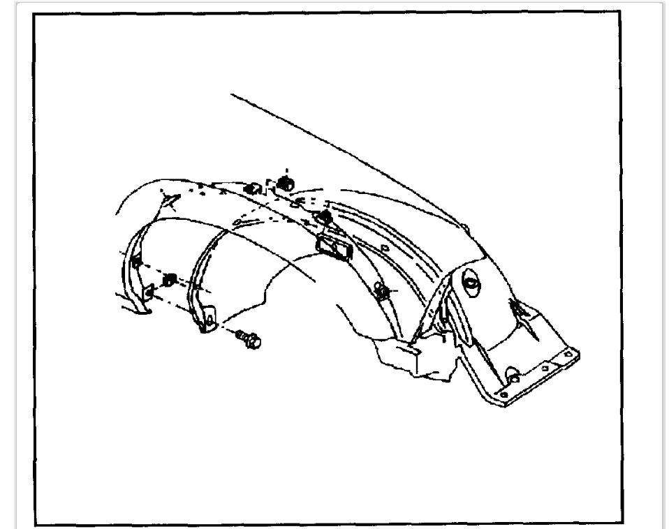
11. On the Utility only, remove the A/C evaporator and blower module heat shield screws.
12. On the Utility only, slide the A/C evaporator and blower module heat shield toward the front of the vehicle.
13. Remove the 2 lower heat/vent module mounting nuts.
14. On the Utility only, remove the A/C evaporator and blower module heat shield bracket.
ImageOpen In New TabZoom/Print
15. Remove the bottom right heat/vent module mounting bolt from inside the vehicle.
IMPORTANT: The heat/vent mounting stud has a flange on the inside and cannot be removed from under the hood. Stop turning the stud after the threads are off the heat/vent module.
16. On the Utility only, while an assistant inside the vehicle pulls the bottom right corner of the heat/vent module approximately 2.5 mm (1 in) back, remove the 2 heat/vent module mounting studs.
17. On vehicles with A/C only, lower the vehicle.
18. On vehicles with a 2.2L engine only, remove the engine wiring harness bracket located at the rear of the intake manifold. Refer to Valve Rocker Arm Cover Replacement in Engine - 2.2L.
19. Remove the HVAC module mounting bolt located at the lower left side of the heater core to heater hose connection.
20. Remove the HVAC module mounting nut located at the lower right side of the heater core to heater connection.
IMPORTANT: The heat/vent mounting stud has a flange on the inside and cannot be removed from under the hood. Stop turning the stud after the threads are off the heat/vent module.
21. On the utility models only, loosen the HVAC module mounting studs until the threads are free from the heat/vent module.
22. Disconnect all of the electrical connectors from the HVAC module.
23. Disconnect all of the vacuum lines from the heater assembly.
24. Disconnect the heater hoses from the heater core.
25. Remove the HVAC module from the vehicle.
INSTALLATION PROCEDURE
1. If replacing the HVAC module, transfer the components from the old heat/vent module as necessary.
IMPORTANT: Before installing the HVAC module to the vehicle, ensure that the HVAC module mounting studs are located in the proper positions.
2. Install the HVAC module to the vehicle.
3. Connect the heater hoses to the heater core.
4. Connect all of the vacuum lines to the heater assembly.
5. Connect all of the electrical connectors to the HVAC module.
6. Install the bottom right HVAC module mounting bolt from inside the vehicle approximately halfway into the threads.
NOTE: Refer to Fastener Notice in Service Precautions.
7. On the Utility only, install the HVAC module mounting stud located at the lower right side of the heater core to heater hoses connection in the engine compartment.
Tighten the HVAC module mounting stud to 4.5 N.M (40 lb in).
8. On vehicles with A/C only, raise the vehicle. Refer to Vehicle Lifting in Maintenance.
9. On the Utility only, install the bottom right HVAC mounting studs. Ask an assistant to pull the bottom right corner of the HVAC module back from inside the vehicle.
Tighten the heat/vent module mounting studs to 4.5 N.M (40 lb in).
10. On the Utility only, install the A/C evaporator and blower module heat shield bracket.
11. Install the heater/vent module mounting nuts.
Tighten the HVAC module mounting nuts to 4.5 N.M (40 lb in).
12. On the Utility only, slide the A/C evaporator and blower module heat shield into the original position.
13. On the Utility only, install the A/C evaporator and blower module heat shield screws.
Tighten the A/C evaporator and blower module heat shield screws 2.2 N.M (19 lb in).
14. On vehicles with A/C only, install the right front tire. Refer to Tire and Wheel Removal and installation in Tires and Wheels.
15. On vehicles with A/C only, lower the vehicle.
16. Install the bottom right HVAC module mounting bolt from inside the vehicle.
Tighten the HVAC module mounting bolt to 4.5 N.M (40 lb in).
17. On vehicles with A/C only, install the right wheel house panel. Refer to Wheelhouse Panel Replacement in Body front End.
18. Install the HVAC module mounting nut located at the lower right side of the heater core to heater connection.
Tighten the HVAC module mounting nut to 4.5 N.M (40 lb in).
19. Install the HVAC module mounting bolt located at the lower left side of the heater core to heater hose connection.
Tighten the HVAC module mounting bolt to 4.5 N.M (40 lb in).
20. On vehicles with the 2.2L engine only, install the engine wiring harness bracket located at the rear of the intake manifold. Refer to Valve Rocker Arm Cover Replacement in Engine - 2.2L.
IMPORTANT: Use the same mounting bolt marked during removal for the HVAC module during the installation process. Other mounting bolts are longer and will obstruct the operation of the temperature door.
21. Install the HVAC module mounting bolt through the blower motor resistor or service access cover opening.
Tighten the HVAC module mounting bolt to 4.5 N.M (40 lb in).
22. On vehicles without automatic climate control, install the blower motor resistor. Refer to Blower Motor Resistor Assembly Replacement (C42) or Blower Motor Resistor Assembly Replacement (C60).
23. On vehicles with automatic climate control only, install the service access cover (2).
24. On vehicles with automatic climate control only, install the service access cover mounting screws (1).
Tighten the screws to 1.9 N.M (17 lb in).
25. On vehicles with automatic climate control only, install the outer layer of the A/C evaporator and blower module.
IMPORTANT: Do not use RTV. Apply the adhesive bead as straight as possible. Allow the adhesive to set for 15 minutes or until the adhesive becomes tacky.
26. Seal the cut line using black weather-strip adhesive.
27. Refill the engine coolant. Refer to Draining and Filling Cooling System in Cooling System.
28. Install the instrument panel.
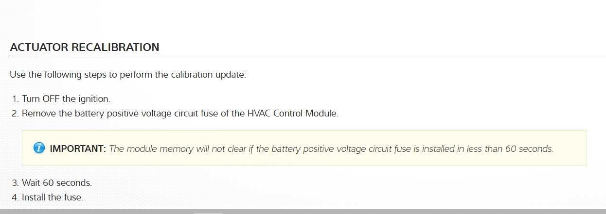
29. Calibrate the HVAC module actuator. Refer to Re-Calibrating Actuators in HVAC Systems - Automatic.
Images (Click to make bigger)
Saturday, December 19th, 2020 AT 10:01 AM
(Merged)