Hi and thanks for using 2CarPros.
I checked for recalls or technical service bulletins and found nothing related to the head gasket. Before I would arbitrarily assume the gasket is bad, I would recommend testing. It isn't hard to do. Here is a link that shows how it is done:
https://www.2carpros.com/articles/head-gasket-blown-test
Now, if you confirm the head gasket is the problem, here are the directions for replacement. All attached pictures correlate with these directions.
___________________________
CYLINDER HEAD
Cylinder Head
Removal
1. With the vehicle in NEUTRAL, position it on a hoist. For additional information, refer to Vehicle Jacking and Lifting See: Vehicle Lifting > Procedures > Jacking and Lifting.
2. Release the fuel system pressure. For additional information, refer to Section 310-00 See: Fuel Delivery and Air Induction > Components > Fuel System.
3. Disconnect the battery ground cable. For additional information, refer to Section 414-01 See: Battery > Removal and Replacement > Battery Disconnect.
4. Remove the Air Cleaner (ACL) outlet tube. For additional information, refer to Section 303-12 See: Fuel Delivery and Air Induction > Components > Fuel System.
5. Remove the Heated Oxygen Sensor (HO2S). For additional information, refer to Section 303-14 .
6. Drain the engine cooling system. For additional information, (SEE Cooling System &/or Engine Block Heater).
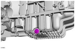
7. Drain the engine oil.
- Install the drain plug.
- Tighten to 28 Nm (21 lb-ft).
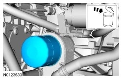
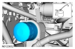
8. Remove and discard the engine oil filter.
9. Remove the Catalyst Monitor Sensor (CMS). For additional information, refer to Section 303-14 .
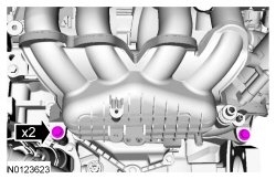
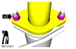
10. Remove the 2 catalytic converter-to-muffler nuts and separate the catalytic converter from the muffler.
- Discard the gasket.
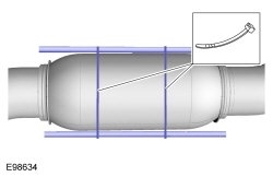
11. NOTICE: Do not excessively bend or twist the exhaust flexible pipe. Failure to follow these instructions may cause damage to the flexible pipe.
Support the exhaust flexible pipe with a support wrap or suitable splint.
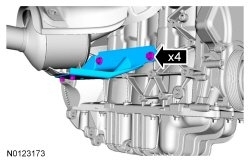
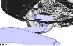
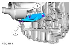
12. Remove the 4 bolts and the lower catalytic converter bracket.
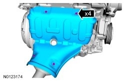
13. Remove the 4 bolts and the catalytic converter heat shield.
14. Remove the 4 catalytic converter nuts and bolt.
- Discard the 4 nuts and bolt.
15. Position the catalytic converter back and secure with mechanic wire.
- Discard the catalytic converter gasket.
16. If equipped, disconnect the block heater electrical connector.
17. Remove the 4 catalytic converter studs and discard.
18. Disconnect the fuel tube spring lock couplings from the fuel rail. For additional information, refer to Section 310-00 See: Fuel Delivery and Air Induction > Components > Fuel System.
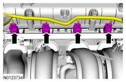
19. Disconnect the 4 fuel injector electrical connectors.
20. Disconnect the Throttle Body (TB) electrical connector.
- Detach the wiring harness retainer from the TB (Throttle Body).
21. Remove the screw and the oil level indicator and tube.
- Inspect and replace the O-ring seal, if necessary.
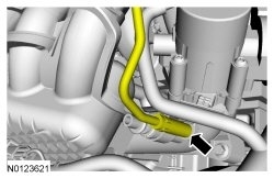
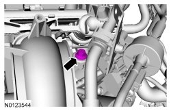
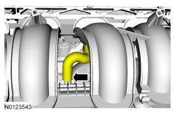
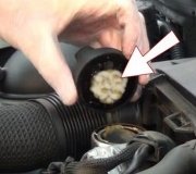
22. Disconnect the PCV hose from the intake manifold.
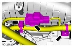
23. Remove the bolt for the Evaporative Emission (EVAP) canister purge valve.
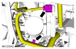
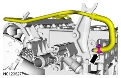
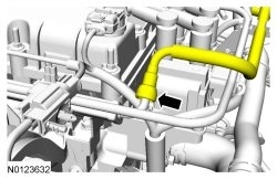
24. Disconnect the brake booster vacuum tube from the intake manifold.
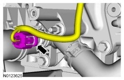
25. Disconnect the EVAP (Evaporative Emission) canister purge valve tube from the intake manifold and position the EVAP (Evaporative Emission) canister purge valve aside.
26. Detach the Knock Sensor (KS) electrical connector from the bottom of the intake manifold.
- Detach the 2 wiring harness retainers from the bottom of the intake manifold.
27. Remove the valve tappets. For additional information, refer to Valve Tappets See: Lifter / Lash Adjuster, Valve > Removal and Replacement > Valve Tappets.
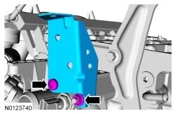
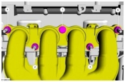
28. Remove the 2 lower bolts for the intake manifold.
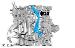
29. Remove the 4 bolts and the timing belt cover backplate.
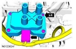
30. Disconnect the ignition coil electrical connector and remove the 4 screws and the ignition coil.
31. Detach the fuel tube retainer from the coolant outlet bracket.
- Detach the 2 wiring harness retainers and the coolant hose retainer from the coolant outlet bracket.
32. If equipped with a manual transaxle, remove the transaxle shift cables from the clip.
33. Remove the nut, bolt and the bracket from the coolant outlet.
34. Disconnect the Engine Coolant Temperature (ECT) sensor electrical connector.
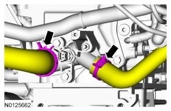
35. Disconnect the 2 coolant hoses from the coolant outlet.
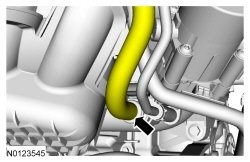
36. Disconnect the coolant return hose from the cylinder head.
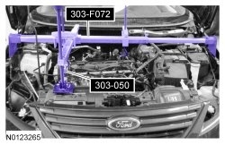
37. Using a floor jack and a block of wood, support the engine.
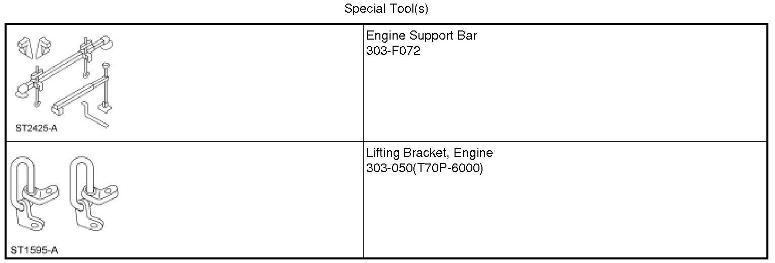
38. Remove the Engine Support Bar.
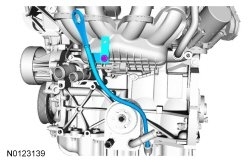
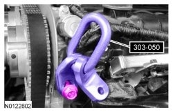
39. Remove the bolt and the Engine Lifting Bracket.
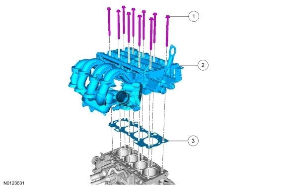
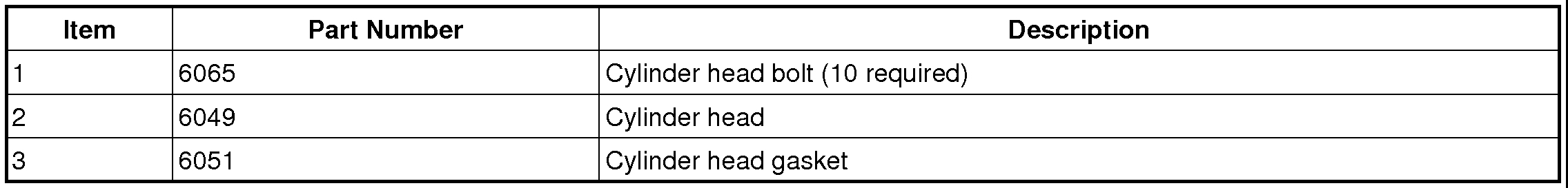
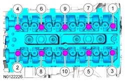
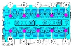
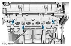
40. NOTE: Make sure that the cylinder head is at ambient air temperature before removing the cylinder head bolts.
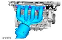
Remove the 10 cylinder head bolts in the sequence shown.
- Remove the cylinder head.
- Discard the cylinder head bolts and gasket.
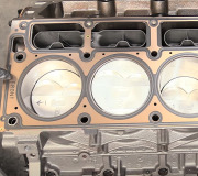
41. Support the cylinder head on a bench with the head gasket side up. Check the cylinder head distortion and the cylinder block distortion. For additional information, refer to Section 303-00 .
Installation
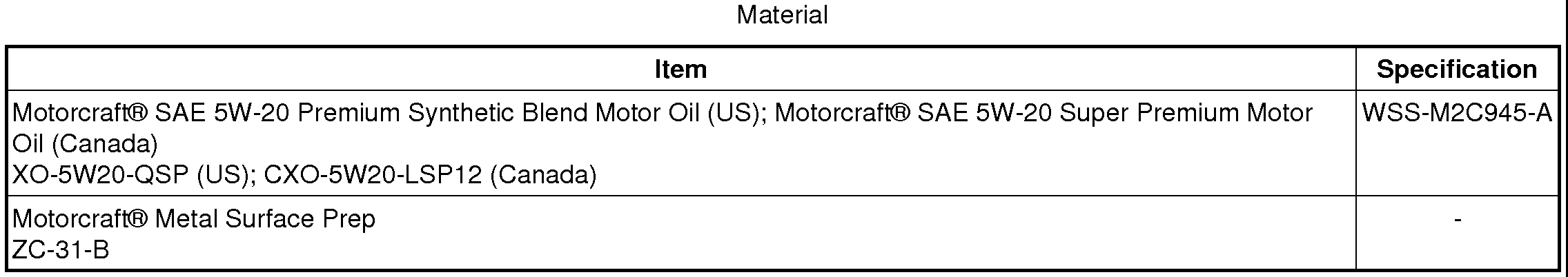
1. NOTICE: Do not use metal scrapers, wire brushes, power abrasive discs or other abrasive means to clean the sealing surfaces. These tools cause scratches and gouges that make leak paths. Use a plastic scraping tool to remove all traces of the head gasket.
NOTE: If there is no residual gasket material present, metal surface prep can be used to clean and prepare the surfaces.
Clean the cylinder head-to-cylinder block mating surface of both the cylinder head and the cylinder block in the following sequence.
1. Remove any large deposits of gasket material with a plastic scraper.
2. Apply metal surface prep, following package directions, to remove any traces of oil or coolant, and to prepare the surfaces to bond with the new gasket. Do not attempt to make the metal shiny. Some staining of the metal surfaces is normal.
2. NOTE: Lubricate the bolts with clean engine oil prior to installation.
Install the cylinder head gasket, cylinder head and 10 new bolts. Tighten the bolts in the sequence shown in 4 stages:
- Stage 1: Tighten to 5 Nm (44 lb-in).
- Stage 2: Tighten to 15 Nm (133 lb-in).
- Stage 3: Tighten to 35 Nm (26 lb-ft).
- Stage 4: Tighten an additional 75 degrees.
3. Using a engine mount bracket bolt, install the Engine Lifting Bracket.
4. Install the Engine Support Bar and support the engine.
5. Remove the floor jack and block of wood.
6. Connect the coolant return hose to the cylinder head.
7. Connect the 2 coolant hoses to the coolant outlet.
8. Connect the ECT (Engine Coolant Temperature) sensor electrical connector.
9. Install the coolant outlet bracket, nut and the bolt.
- Tighten to 6 Nm (53 lb-in).
10. If equipped with a manual transaxle, install the transaxle shift cables to the clip.
11. Attach the fuel tube retainer to the coolant outlet bracket.
- Attach the 2 wiring harness and coolant hose retainers to the coolant outlet bracket.
12. Install the ignition coil, 4 screws and connect the ignition coil electrical connector.
- Tighten to 6 Nm (53 lb-in).
13. Install the timing belt cover backplate and the 4 bolts.
- Tighten to 9 Nm (80 lb-in).
14. Install the 2 lower bolts for the intake manifold.
- Tighten to 18 Nm (159 lb-in).
15. Install the valve tappets. For additional information, refer to Valve Tappets See: Lifter / Lash Adjuster, Valve > Removal and Replacement > Valve Tappets.
16. Attach the KS (Knock Sensor) electrical connector to bottom of the intake manifold.
- Attach the 2 wiring harness retainers to the bottom of the intake manifold.
17. Position and connect the EVAP (Evaporative Emission) canister purge valve tube to the intake manifold.
18. Connect the brake booster vacuum tube to the intake manifold.
19. Install the bolt for the EVAP (Evaporative Emission) canister purge valve.
- Tighten to 9 Nm (80 lb-in).
20. Connect the PCV hose to the intake manifold.
21. NOTE: Lubricate the O-ring seal with clean engine oil.
Install the oil level indicator and tube and the screw.
- Tighten to 4 Nm (35 lb-in).
22. Connect the TB (Throttle Body) electrical connector.
- Attach the wiring harness retainer to the TB (Throttle Body).
23. Connect the 4 fuel injector electrical connectors.
24. Connect the fuel tube spring lock couplings to the fuel rail. For additional information, refer to Section 310-00 See: Fuel Delivery and Air Induction > Components > Fuel System.
25. Install the 4 new catalytic converter studs.
- Tighten to 17 Nm (150 lb-in).
26. If equipped, connect the block heater electrical connector.
27. Using a new gasket, position the catalytic converter and install the 4 new nuts and bolt finger tight.
28. NOTICE: Failure to tighten the catalytic converter manifold fasteners in 20 Nm increments until reaching final torque of 55 Nm will cause the converter to develop an exhaust leak.
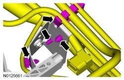
Tighten the bolt and 4 nuts in the sequence shown, in 3 stages.
- Stage 1: Tighten all fasteners in sequence to 20 Nm (177 lb-in).
- Stage 2: Tighten all fasteners in sequence to 40 Nm (30 lb-ft).
- Stage 3: Tighten all fasteners in sequence to 55 Nm (41 lb-ft).
29. Install the catalytic converter heat shield and the 4 bolts.
- Tighten to 10 Nm (89 lb-in).
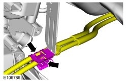
30. Install the lower catalytic converter bracket and the 4 bolts and tighten in sequence shown.
1. Tighten the catalytic converter bracket-to-engine block bolts to 50 Nm (37 lb-ft).
2. Tighten the catalytic converter bracket-to-catalytic converter bolts to 25 Nm (18 lb-ft).
31. NOTICE: Do not excessively bend or twist the exhaust flexible pipe. Failure to follow these instructions may cause damage to the flexible pipe.
Remove the support for the exhaust flexible pipe.
32. Using a new gasket, position the catalytic converter to the muffler and install the 2 catalytic converter nuts.
- Tighten to 48 Nm (35 lb-ft).
33. Install the CMS (Catalyst Monitor Sensor). For additional information, refer to Section 303-14 .
34. NOTE: Lubricate the engine oil filter gasket with clean engine oil prior to installing the oil filter.
Install a new engine oil filter.
- Tighten to 15 Nm (133 lb-in).
35. Install the HO2S (Heated Oxygen Sensor). For additional information, refer to Section 303-14 .
36. Install the ACL (Air Cleaner) outlet tube. For additional information, refer to Section 303-12 See: Fuel Delivery and Air Induction > Components > Fuel System.
37. Connect the battery ground cable. For additional information, refer to Section 414-01 See: Battery > Removal and Replacement > Battery Disconnect.
38. Fill the engine with clean engine oil.
39. Fill the engine cooling system. For additional information, (SEE Cooling System &/or Engine Block Heater).
__________________________
Let me know if this helps or if you have other questions
Take care,
Joe
Images (Click to make bigger)
Friday, January 11th, 2019 AT 7:55 PM