Hi,
Chances are the rheostat on the level gauge has failed. To check it will require a multimeter or voltmeter to check resistance. Here are the directions:
___________________________________
2001 Dodge or Ram Truck RAM 1500 Truck 2WD V8-5.9L VIN Z LDC
Component Tests and General Diagnostics
Vehicle Powertrain Management Fuel Delivery and Air Induction Fuel Tank Fuel Gauge Sender Testing and Inspection Component Tests and General Diagnostics
COMPONENT TESTS AND GENERAL DIAGNOSTICS
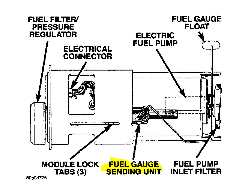
The fuel gauge sending unit contains a variable resistor (track). As the float moves up or down, electrical resistance will change. To test the gauge sending unit only, it must be removed from vehicle. The unit is part of the fuel pump module. Refer to Fuel Pump Module Removal/Installation for procedures. Measure the resistance across the sending unit terminals. With float in up position, resistance should be 20 ohms ± 6 ohms. With float in down position, resistance should be 220 ohms ± 6 ohms.
_________________________________
Now, if you find there is no resistance or no resistance, you will need to replace it. It is located on the fuel pump module in the tank. Pic 1 shows the location of the sensor (rheostat).
_______________________________
Here are the directions for repairing it, but in all honesty, you are better off jus getting a new pump because it should come with a new sender
2001 Dodge or Ram Truck RAM 1500 Truck 2WD V8-5.9L VIN Z LDC
Fuel Level Sending Unit/Sensor Replacement
Vehicle Powertrain Management Fuel Delivery and Air Induction Fuel Tank Fuel Gauge Sender Service and Repair Procedures Fuel Level Sending Unit/Sensor Replacement
FUEL LEVEL SENDING UNIT/SENSOR REPLACEMENT
REMOVAL
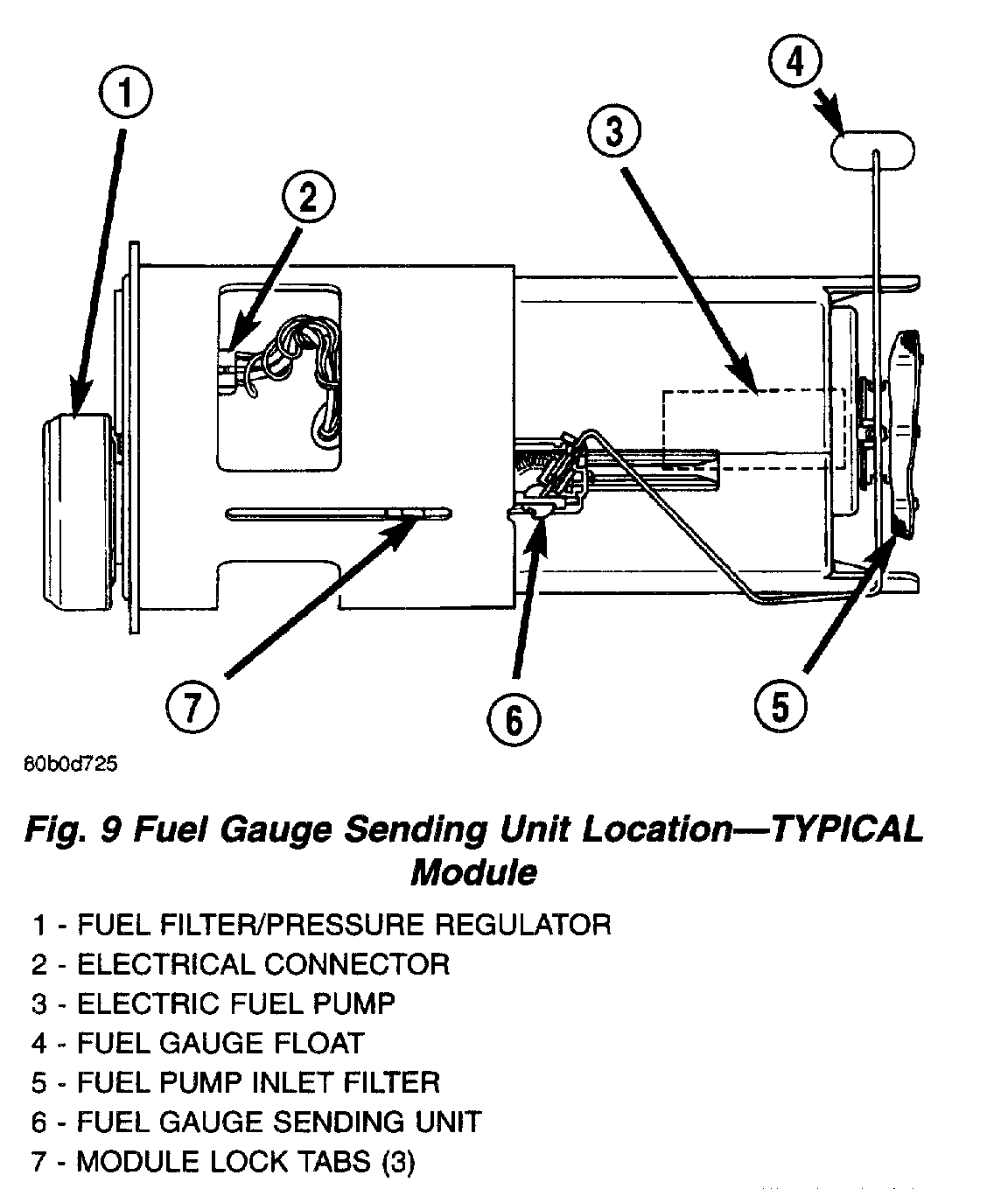
Fig. 9 Fuel Gauge Sending Unit Location - Typical Module
pic 2
The fuel gauge sending unit (fuel level sensor) and float assembly is located on the side of fuel pump module (Fig. 9). The fuel pump module is located inside of fuel tank.
1. Remove fuel tank.
2. Remove fuel pump module. Refer to Fuel Pump Module Removal/Installation.
3. Unplug 4-way electrical connector (Fig. 9).
4. Disconnect 2 sending unit wires at 4-way connector. The locking collar of connector must be removed before wires can be released from connector. Note location of wires within 4-way connector.
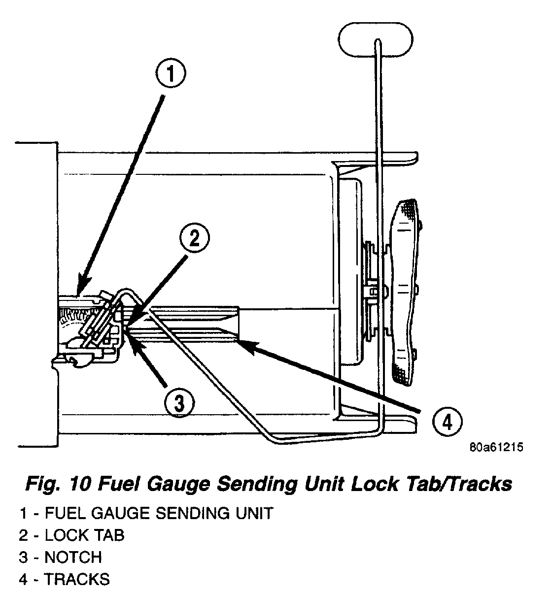
Fig. 10 Fuel Gauge Sending Unit Lock Tab/Tracks
pic 3
5. The sending unit is retained to pump module with a small lock tab and notch (Fig. 10). Carefully push lock tab to the side and away from notch while sliding sending unit downward on tracks for removal. Note wire routing while removing unit from module.
INSTALLATION
The fuel gauge sending unit (fuel level sensor) and float assembly is located on the side of fuel pump module (Fig. 9). The fuel pump module is located inside of fuel tank.
1. Position sending unit into tracks. Note wire routing.
2. Push unit on tracks until lock tab snaps into notch.
3. Connect 2 sending unit wires into 4-way connector and install locking collar.
4. Connect 4-way electrical connector to module.
5. Install fuel pump module. Refer to Fuel Pump Module Removal/Installation.
6. Install fuel tank.
__________________________
Here are the directions for the removal and replacement of the fuel tank. The attached pics correlate with the directions.
__________________________
2001 Dodge or Ram Truck RAM 1500 Truck 2WD V8-5.9L VIN Z LDC
Fuel Tank Removal and Installation
Vehicle Powertrain Management Fuel Delivery and Air Induction Fuel Tank Service and Repair Procedures Fuel Tank Removal and Installation
FUEL TANK REMOVAL AND INSTALLATION
REMOVAL
Warning: the fuel system is under a constant pressure even with the engine off. Before servicing the fuel tank, fuel system pressure must be released. Refer to the fuel system pressure release procedure before servicing the fuel tank.
Two different procedures may be used to drain fuel tank (lowering tank or using DRB scan tool).
The quickest draining procedure involves lowering the fuel tank.
In this engine: As an alternative procedure, the electric fuel pump may be activated allowing tank to be drained at fuel rail connection. Refer to DRB scan tool for fuel pump activation procedures. Before disconnecting fuel line at fuel rail, release fuel pressure. Refer to the Fuel System Pressure Release Procedure for procedures. Attach end of special test hose tool number 6541, 6539, 6631 or 6923 at fuel rail disconnection (tool number will depend on model and/or engine application). Position opposite end of this hose tool to an approved gasoline draining station. Activate fuel pump and drain tank until empty.
If electric fuel pump is not operating, tank must be lowered for fuel draining. Refer to following procedures.
1. Remove fuel tank filler tube cap.
2. Perform Fuel System Pressure Release procedure.
3. In this engine: Disconnect negative battery cable at battery.
4. Raise vehicle on hoist.
5. Certain models are equipped with a separate grounding wire (strap) connecting the fuel fill tube assembly to the body. Disconnect wire by removing screw.
6. Open fuel fill door and remove screws mounting fuel filler tube assembly to body. Do not disconnect rubber fuel fill or vent hoses from tank at this time.
7. Place a transmission jack under center of fuel tank. Apply a slight amount of pressure to fuel tank with transmission jack.
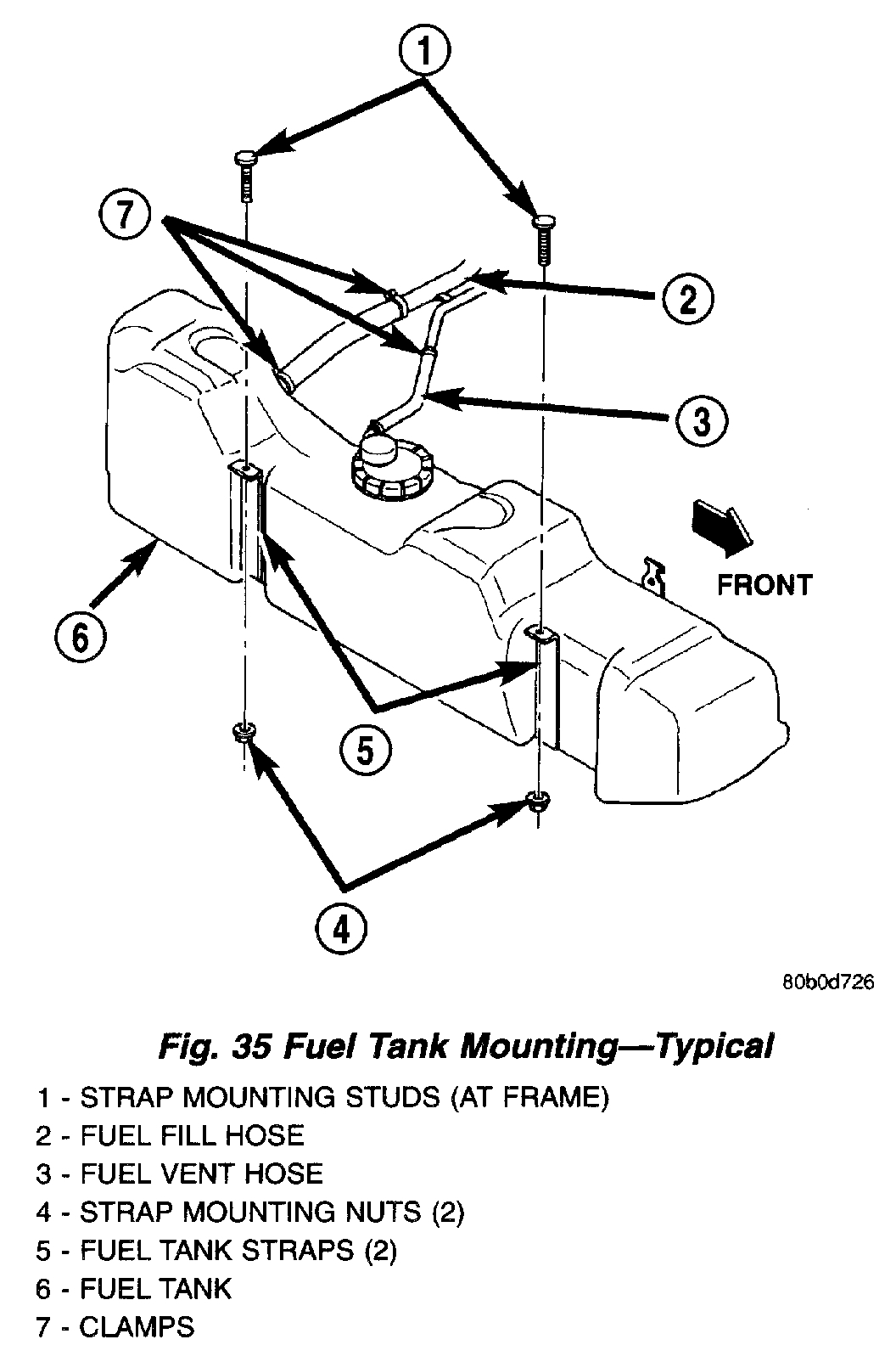
Fig. 35 Fuel Tank Mounting - Typical
pic 4
8. Remove fuel tank mounting strap nuts from mounting strap studs (Fig. 35). If equipped, remove fuel tank shield bolts.
9. Lower fuel tank only enough to allow access to top of tank. The 2 tank fittings (where rubber fuel fill and vent hose connections are made) must be positioned above tank level. Rotate tank slightly to allow these fittings to be above tank level.
WARNING: WRAP SHOP TOWELS AROUND HOSES TO CATCH ANY GASOLINE SPILLAGE.
10. While working over left rear tire/wheel, disconnect rubber fuel vent hose at fuel tank (Fig. 35) (vent hose is the smallest of 2 hoses). Position fuel siphoning/drain hose into this fitting at tank. Drain fuel into an approved portable holding tank or a properly labeled gasoline safety container.
11. Disconnect rubber fuel fill hose at fuel tank (Fig. 35).
12. This Engine:
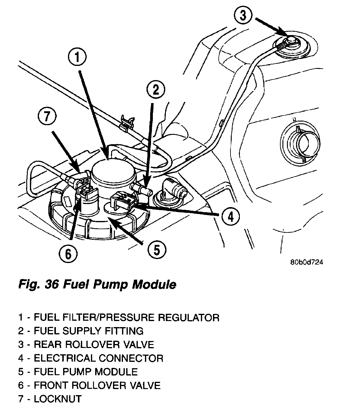
Fig. 36 Fuel Pump Module
pic 5
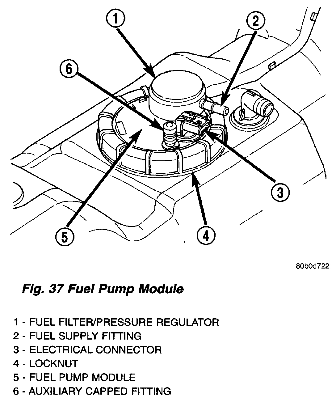
Fig. 37 Fuel Pump Module
pic 6
a. While working over left rear tire/wheel, disconnect wiring harness connector from electrical connector at top of fuel pump module (Fig. 36) or (Fig. 37).
b. If equipped with 26 or 34 gallon fuel tank, two EVAP lines are connected to rollover valves. Disconnect EVAP line from rollover valve at top of module (Fig. 36). Disconnect other EVAP line from rollover valve near rear of tank (Fig. 36).
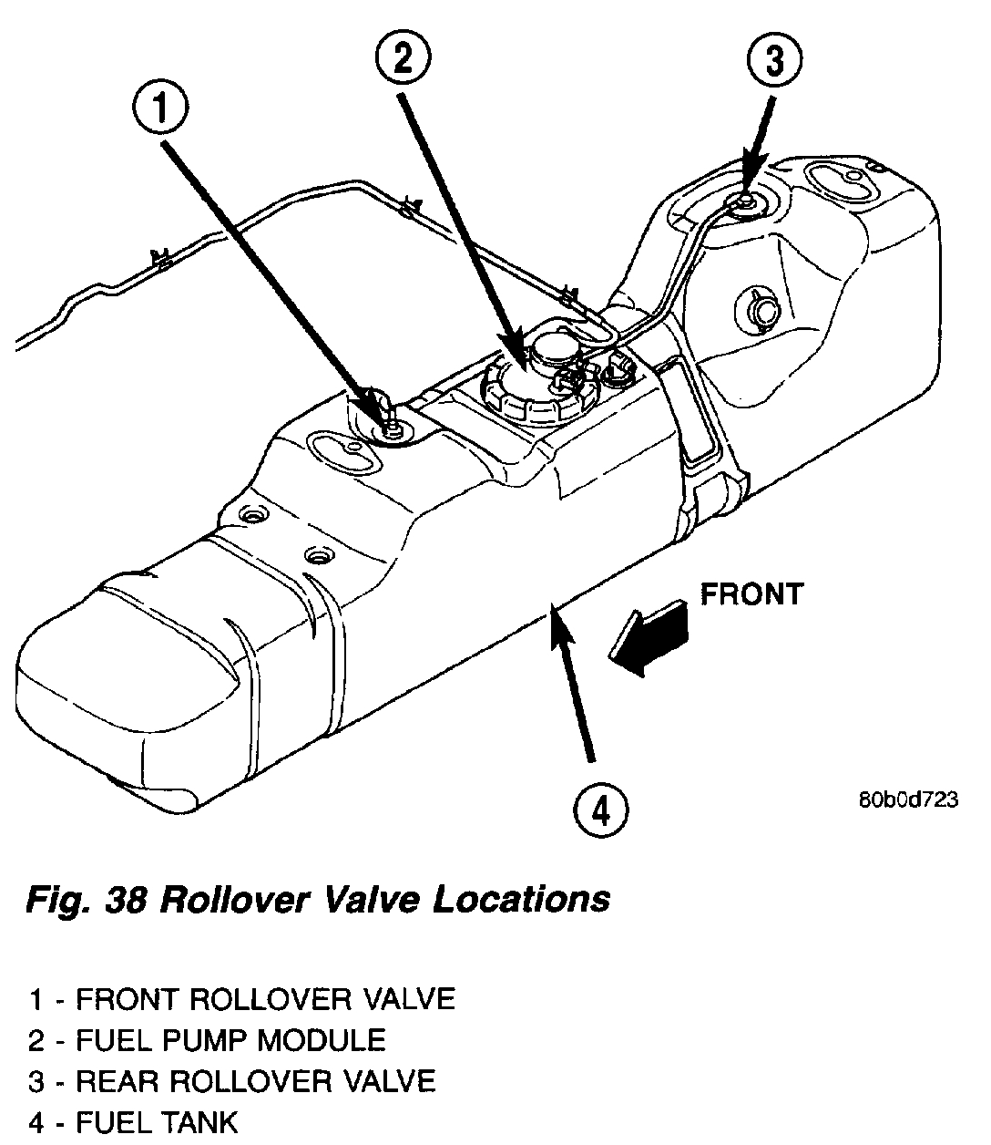
Fig. 38 Rollover Valve Locations
pic 7
c. If equipped with 35 gallon fuel tank, two EVAP lines are connected to rollover valves. Disconnect EVAP lines from rollover valves at top-front and top-rear of fuel tank (Fig. 38).
d. Disconnect fuel supply line at fuel filter/fuel pressure regulator supply fitting (Fig. 36) or (Fig. 37). Refer to Quick-Connect Fittings for procedures.
13. If fuel pump module removal is necessary, refer to Fuel Pump Module Removal/installation.
INSTALLATION
1. In this engine: If fuel pump module is being installed, refer to Fuel Pump Module Removal/installation.
2. Place fuel tank on top of transmission jack.
3. Install rubber fill and vent lines to tank. Tighten hose clamps to 2.3 Nm (20 in. lbs.) torque.
4. Raise tank into position while guiding fill and vent hoses to body. Raise tank only enough to allow access to top of tank.
5. This Engine:
a. Connect electrical connector to fuel pump module.
b. Connect EVAP hoses at rollover valves.
c. Connect fuel supply line at fuel filter/fuel pressure regulator. Refer to Quick-Connect Fittings for procedures.
6. Connect two mounting straps and mounting strap nuts.
7. Tighten strap nuts to 41 Nm (30 ft. lbs.) torque. Do not over tighten retaining strap nuts.
8. Remove transmission jack.
9. Connect fuel filler tube assembly to body.
10. If equipped, connect grounding wire (strap) and screw.
11. Refill fuel tank and inspect all hoses and lines for leaks.
12. Connect negative battery cable(s) to battery(s).
________________________
Let me know what you find or if you have other questions.
Take care,
Joe
Images (Click to enlarge)
Dec 16, 2020 at 3:19 PM