First, here are the directions specific to your vehicle and this specific code. The attached pics correlate with the directions.
___________________________
2000 Chevy Truck K 1500 Suburban 4WD V8-5.3L VIN T
P0452
Vehicle ALL Diagnostic Trouble Codes ( DTC ) Testing and Inspection P Code Charts P0452
P0452
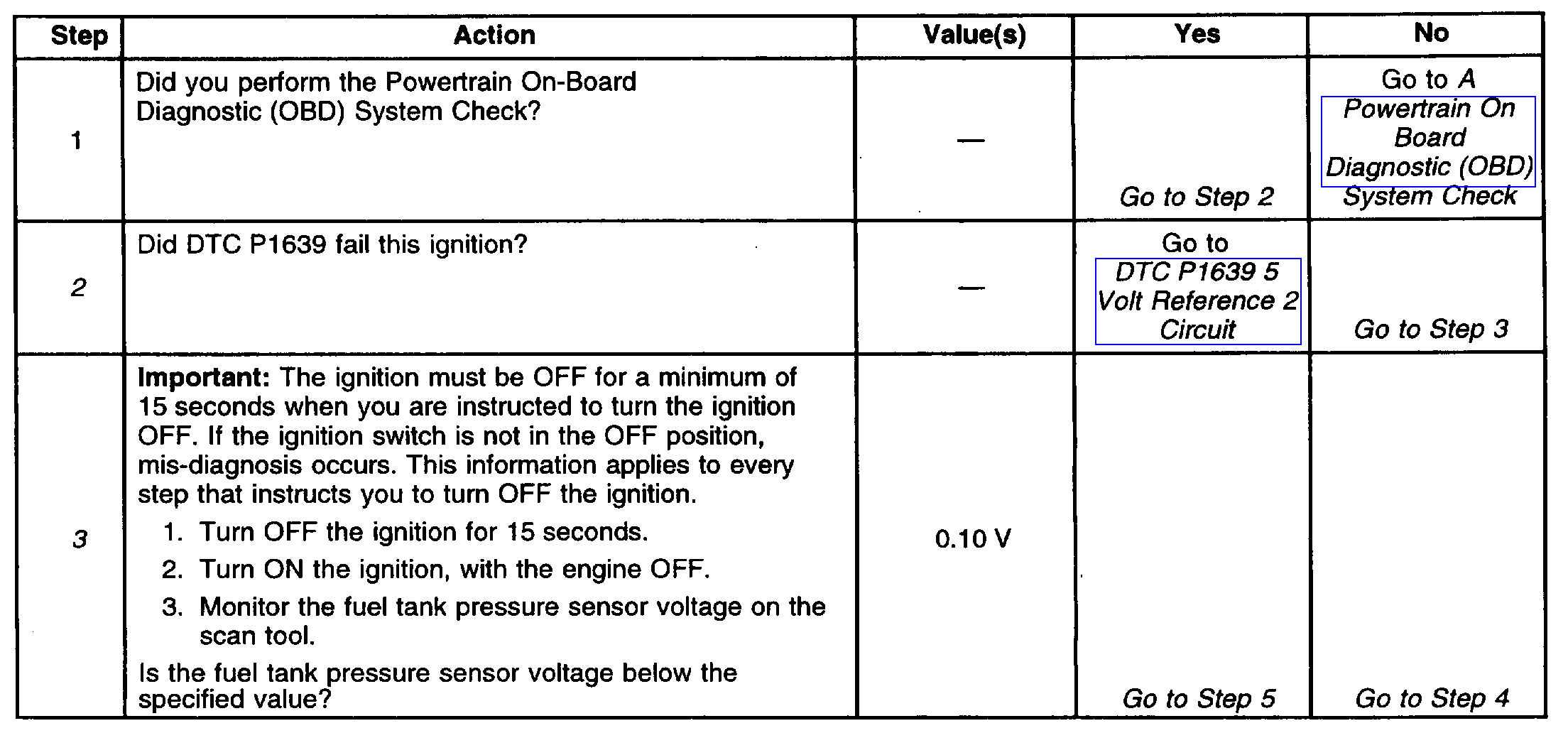
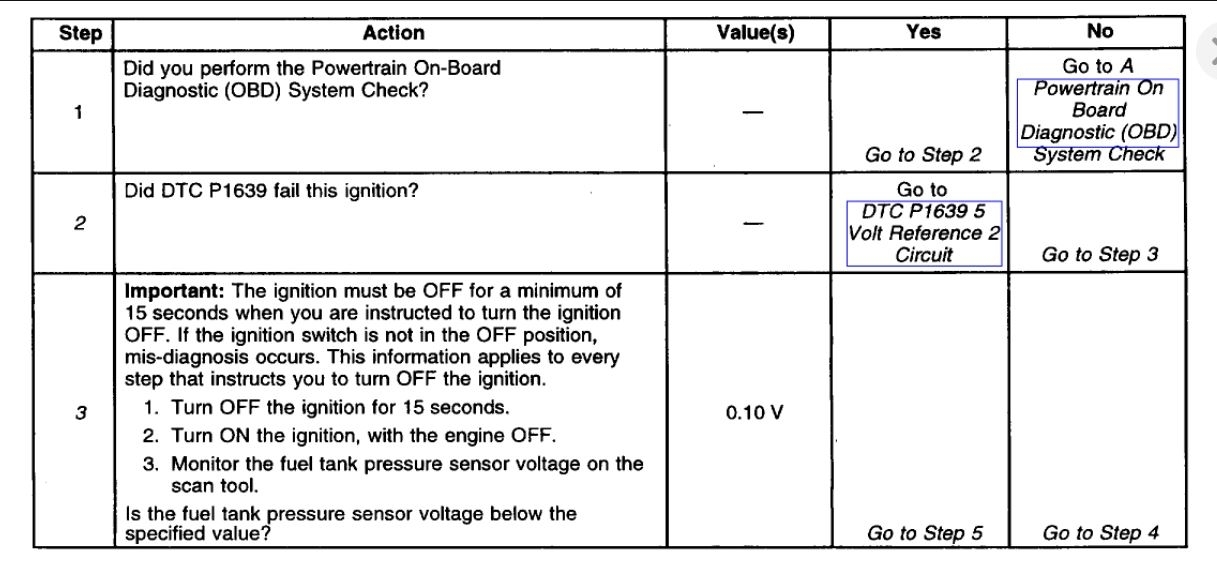
Diagnostic Chart (Part 1 Of 3)
pic 1
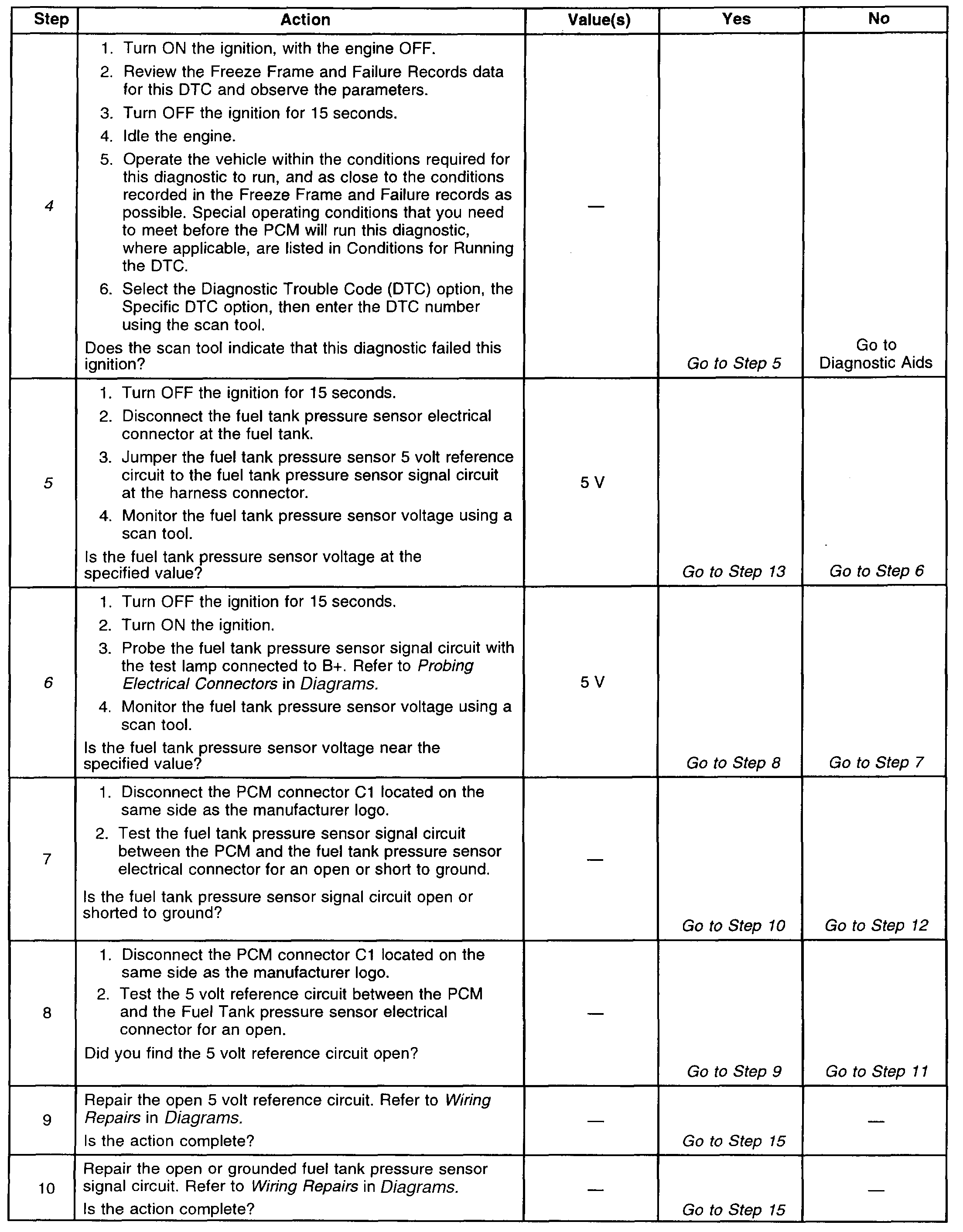
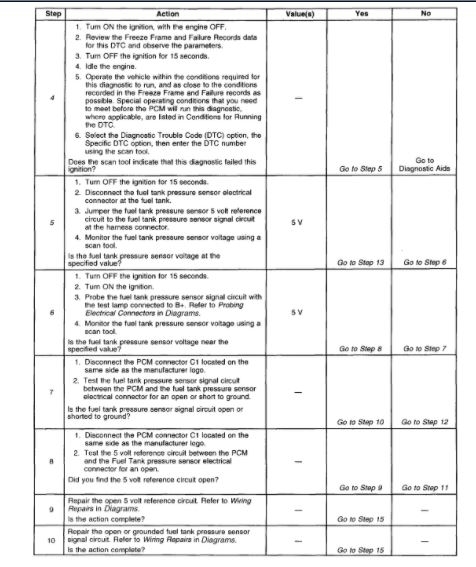
Diagnostic Chart (Part 2 Of 3)
pic 2
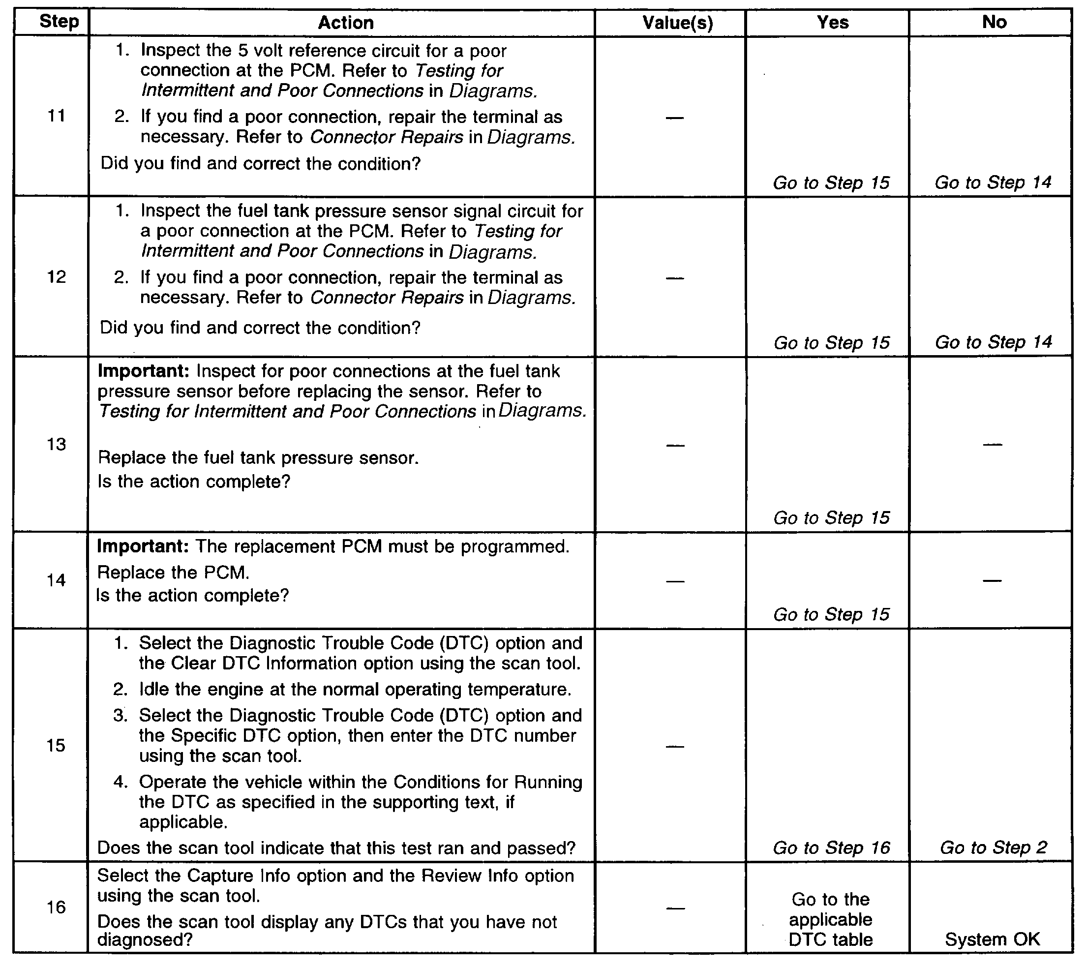
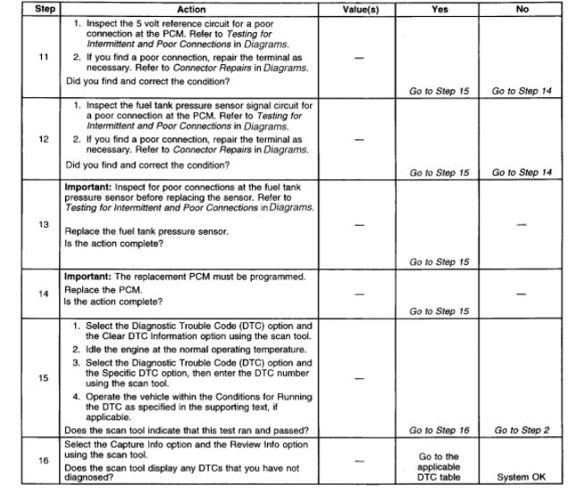
Diagnostic Chart (Part 3 Of 3)
pic 3
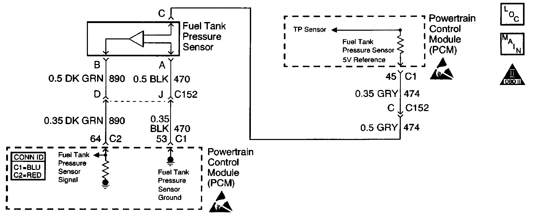
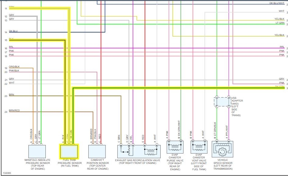
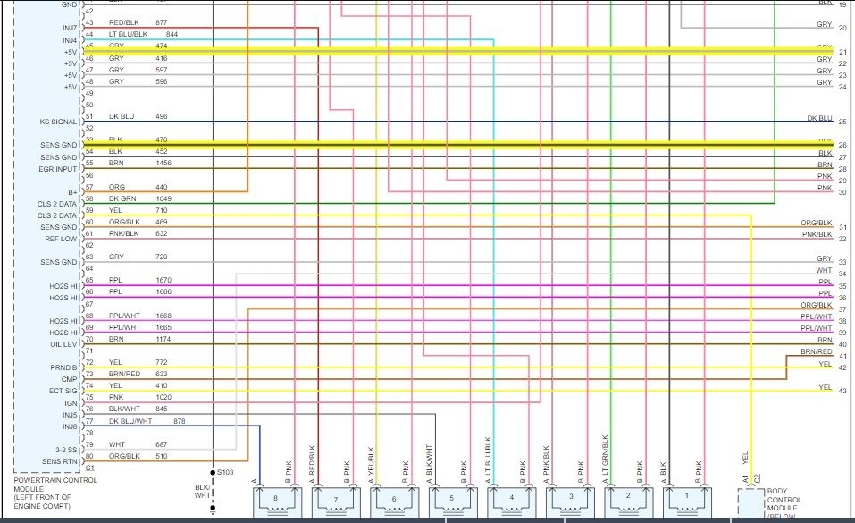
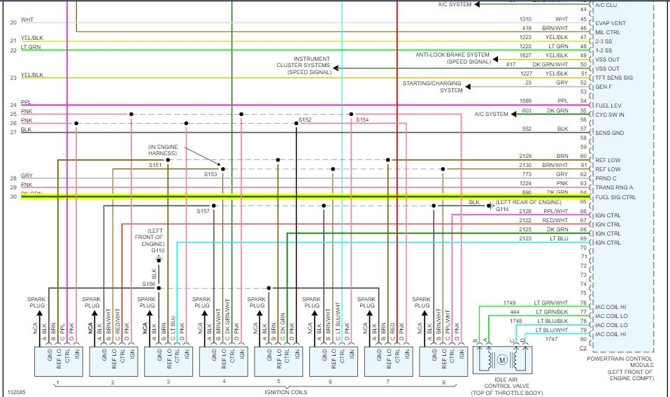
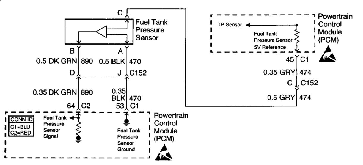
Schematic
pic 4
CIRCUIT DESCRIPTION
The fuel tank pressure sensor changes resistance based on the fuel tank pressure, or vacuum. A vacuum is considered negative pressure.
The Powertrain Control Module (PCM) provides a 5 volt reference and a ground. The fuel tank pressure sensor signal varies between ground and 5 volts as the fuel tank pressure varies. The fuel tank pressure sensor voltage increases as the fuel tank pressure decreases, such as negative pressure, or vacuum. The fuel tank pressure sensor voltage decreases, such as positive pressure, or low voltage, as the fuel tank pressure increases. The PCM uses the fuel tank pressure sensor voltage for Evaporative Emission (EVAP) system leak detection. This DTC sets when the fuel tank pressure sensor signal goes below a predetermined value.
CONDITIONS FOR RUNNING THE DTC
The ignition switch is in the RUN position.
CONDITIONS FOR SETTING THE DTC
^ The fuel tank pressure sensor voltage is less than 0.1 volts.
^ All conditions are present for more than 5 seconds.
ACTION TAKEN WHEN THE DTC SETS
^ The PCM illuminates the Malfunction Indicator Lamp (MIL) on the second consecutive ignition cycle that the diagnostic runs and fails.
^ The PCM records the operating conditions at the time the diagnostic fails. The first time the diagnostic fails, the PCM stores this information in the Failure Records. If the diagnostic reports a failure on the second consecutive ignition cycle, the PCM records the operating conditions at the time of the failure. The PCM writes the conditions to the Freeze Frame and updates the Failure Records.
CONDITIONS FOR CLEARING THE MIL/DTC
^ The PCM turns OFF the Malfunction Indicator Lamp (MIL) after 3 consecutive ignition cycles that the diagnostic runs and does not fail.
^ A last test failed, or current DTC, clears when the diagnostic runs and does not fail.
^ A history DTC clears after 40 consecutive warm-up cycles, if no failures are reported by this or any other emission related diagnostic.
^ Use a scan tool in order to clear the MIL and the DTC.
DIAGNOSTIC AIDS
IMPORTANT: Remove any debris from the PCM connector surfaces before servicing the PCM. Inspect the PCM connector gaskets when diagnosing or replacing the PCM. Ensure that the gaskets are installed correctly. The gaskets prevent water intrusion into the PCM.
For an intermittent, refer to Symptoms. See: Computers and Control Systems > Symptom Related Diagnostic Procedures
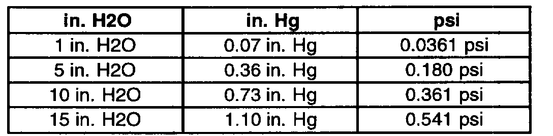
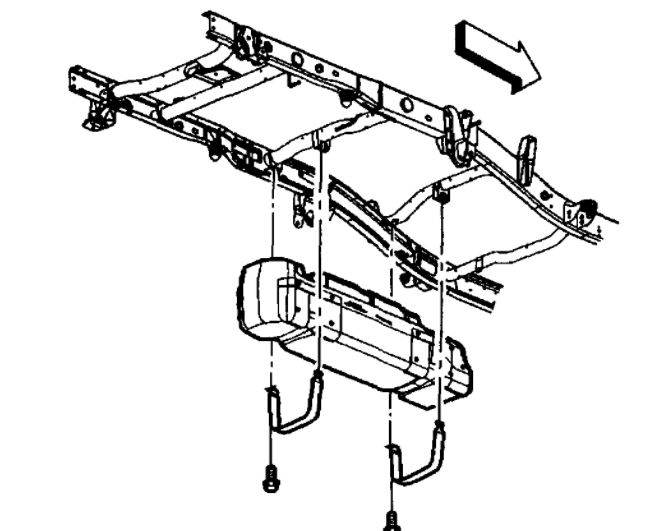
The EVAP pressure sensor range is from +7.5 in. H2O of pressure to -17.5 in. H2O of pressure or vacuum. Inspect for poor connections at connector C152. This connector is located under the underhood electrical center. Refer to Testing for Intermittent and Poor Connections in Diagrams.
pic 5
The vacuum and pressure in the EVAP system is measured in inches of Water (H2O). Most gauges measure vacuum in inches of Mercury (Hg) and pressure in pounds Per Square Inch (psi). The following shows how the values compare:
TEST DESCRIPTION
The numbers below refer to the step numbers on the diagnostic table.
2. If DTC P1639 sets at the same time, this indicates that the 5.0 voltage reference circuit is shorted to a ground. The 5.0 volt reference circuit is internally connected within the PCM.
3. This step determines if the condition is present.
4. Using the Freeze Frame and Failure Records data may aid in locating an intermittent condition. If you cannot duplicate the DTC, the information included in the Freeze Frame and Failure Records data can help determine how many miles since the DTC set. The Fail Counter and Pass Counter can also help determine how many ignition cycles the diagnostic reported a pass or a fail. Operate the vehicle within the same Freeze Frame conditions, such as RPM, load, vehicle speed, temperature etc., that you observed. This will isolate when the DTC failed.
5. If the scan tool displays 5.0 volts, the fuel tank pressure sensor signal circuit and the PCM are okay.
6. This step determines if the signal circuit is open.
___________________________
Let me know if this helps or if you have other questions.
Take care,
Joe
Images (Click to enlarge)
Jan 15, 2021 at 5:37 AM