Fuel pump wiring diagram needed

Tiny
KELLON B.
  • MEMBER
  • 2007 TOYOTA CAMRY
  • 2.4L
  • 4 CYL
  • 2WD
  • AUTOMATIC
  • 100,000 MILES
Can someone please provide the wiring diagram for my fuel pump? From the fuel pump to the diver side kick panel. The connectors at the kick panel are corroded and multiple wires are broken off. Got everything except for one of the fuel pump wires connected.
Monday, May 23rd, 2022 AT 9:59 AM

5 Replies

Tiny
AL514
  • MECHANIC
  • 4,109 POSTS
Hello, the first diagram is the fuel pump and the C/OPN Relay. The relay gets its power from the Instrument Panel Junction Box coming from the IGN Fuse 10amp. The relay is controlled on the Ground side by the ECM. As you can see the wiring changes color from the IGN fuse from yellow to light green at the A58 Junction (third diagram). I'm assuming that you don't have power at the C/OPN Relay or just no power at the pump?
It's tough when you have a corroded fuse panel, the back side of them can turn into a real mess sometimes.

https://www.2carpros.com/articles/how-to-check-wiring

https://www.2carpros.com/articles/how-to-check-an-electrical-relay-and-wiring-control-circuit
Was this
answer
helpful?
Yes
No
Monday, May 23rd, 2022 AT 11:20 AM
Tiny
KELLON B.
  • MEMBER
  • 6 POSTS
Thank you very much. I managed to locate every wire from the pump except for the pink wire. The car now starts, but can you provide a pinout of the a58 black plug? Maybe that will help me find the correct spot. Thank you
Was this
answer
helpful?
Yes
No
Monday, May 23rd, 2022 AT 11:43 AM
Tiny
AL514
  • MECHANIC
  • 4,109 POSTS
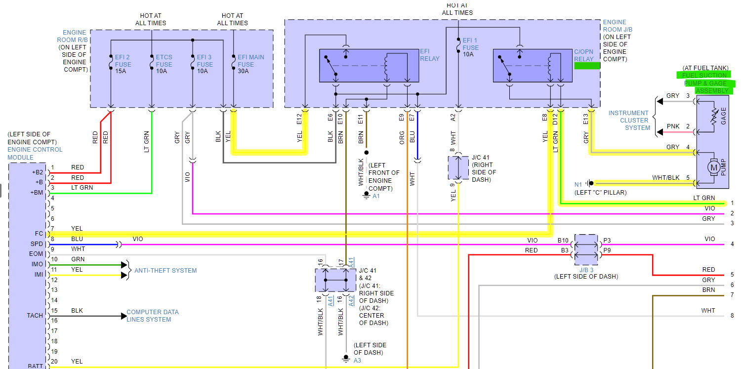
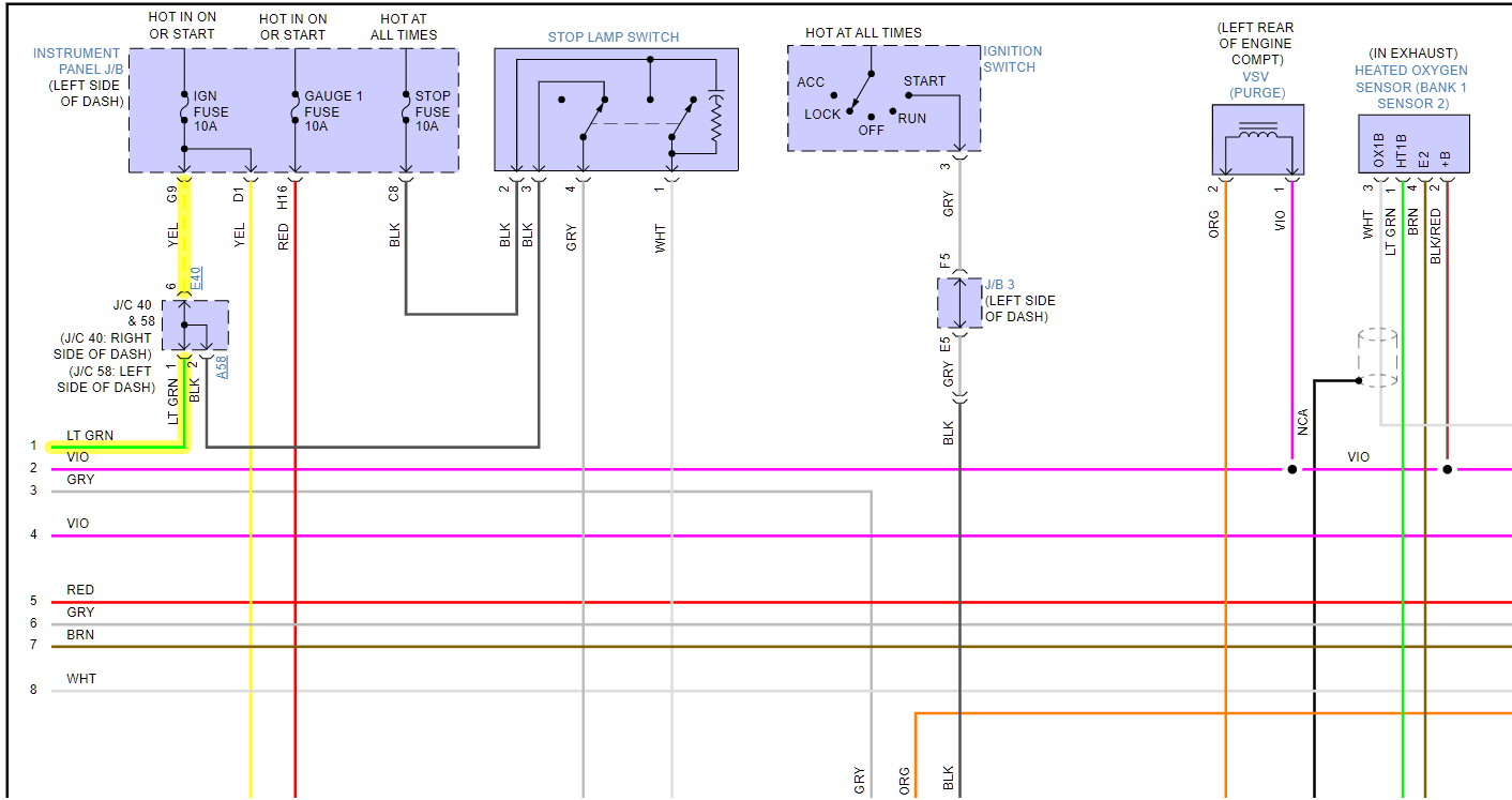
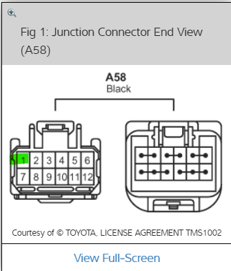
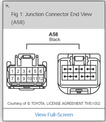
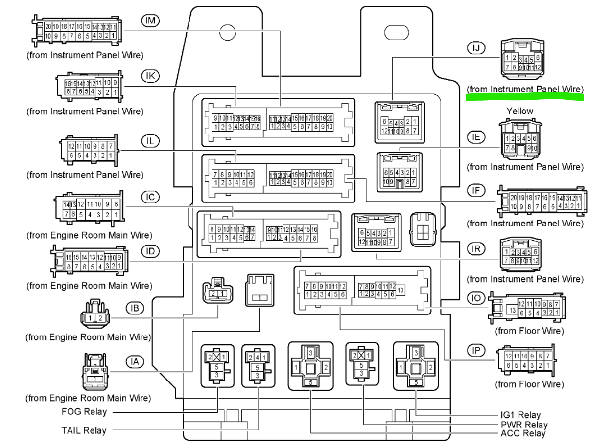
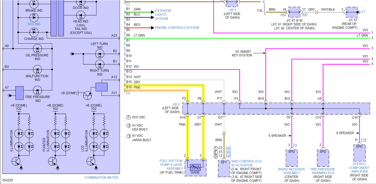
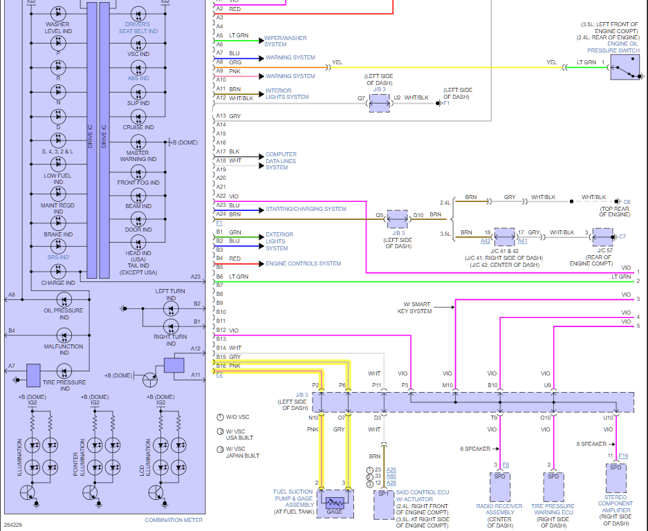
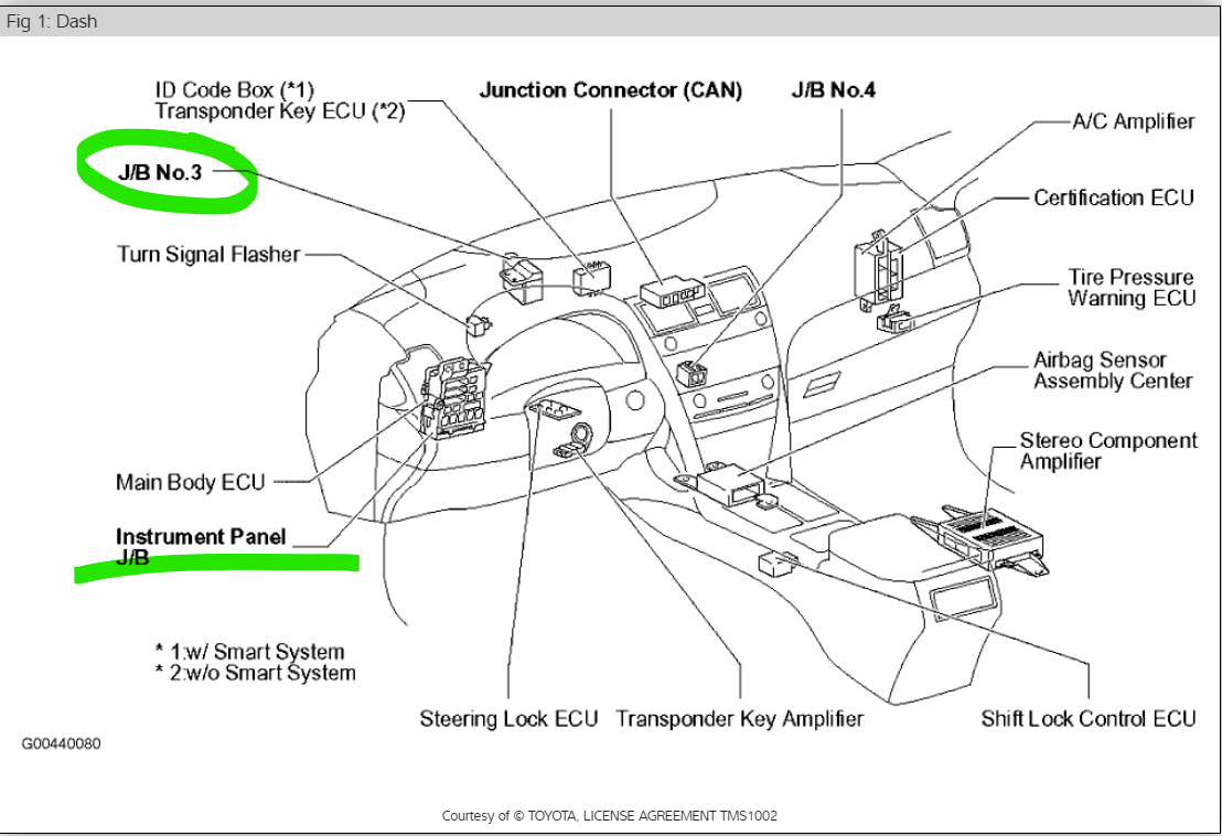
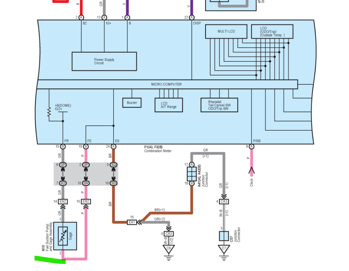
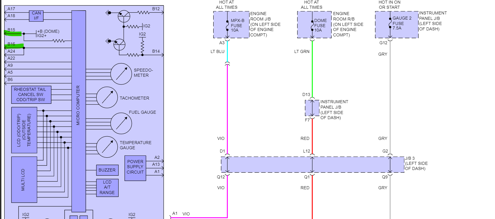
Okay so, you're talking about the pink wire coming from the fuel pump area. I only see 1 pink wire and one other grey wire besides the Fuel Pump feed wire which is also grey. I think what you're seeing is the pink and grey wires that are for the Fuel Gauge. The A58 connector doesn't have any pinout unfortunately. I've looked everywhere and all I can find are these two diagrams (1st 2). In the 2nd diagram I believe that is the A58 Connector coming out of that panel on the driver's side. It's the only 12 pin connector that matched up. But I don't think that is what you are looking for. The third diagram is the Fuel Gauge sending unit to the instrument Cluster. Thats the big purple colored component to the left. The gauge wires run through the J/B 3 connector. Finding that J/B #3 was really tough, but it's up on the driver's side, looks like it's more up above the gas pedal area. The 6th diagram is the fuel gauge circuit it's the OEM from Toyota, and not very helpful. But you can see where that pink wire goes and what it's for. And on the seventh diagram are the pins inside the instrument cluster for pins # B15 and B16 which is the fuel gauge circuitry. So, it should have 12volts going out on one of those wires and then you can see on B15 it has a resistor coming off that circuit inside the cluster, so that would be a voltage sensing circuit coming off that resistor for the gauge reading. Hopefully this all will give you what you need. Sorry it took a while to find all this.
Was this
answer
helpful?
Yes
No
Monday, May 23rd, 2022 AT 5:55 PM
Tiny
KELLON B.
  • MEMBER
  • 6 POSTS
Sorry for the late response but thank you very much for your help in finding those wires. You were spot on with your answers. Also appreciate you digging so deep to provide the information.
Was this
answer
helpful?
Yes
No
Friday, May 27th, 2022 AT 5:12 PM
Tiny
AL514
  • MECHANIC
  • 4,109 POSTS
That's okay, so you got everything working correctly? Thats all that matters.
Was this
answer
helpful?
Yes
No
Friday, May 27th, 2022 AT 6:36 PM

Please login or register to post a reply.

Sponsored links