Hello .. thanks for the donation .. much appreciated
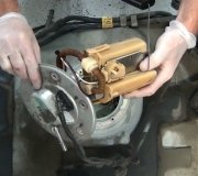
The sender you are looking for is located on the top of the fuel tank .. hope this helps .. let me know
FUEL LEVEL GAUGE
1)Turn ignition off. Unplug connector from fuel level sending unit, located at fuel tank. Connect one terminal of Gauge Tester (021-00055) to Yellow/White wire at harness connector. Connect other wire to Black/Yellow wire at connector.
2)Set tester to 22 OHMS position. Turn ignition on. Wait 60 seconds. Observe fuel gauge. If gauge indicates "E", go to step 5). If gauge does not indicate "E", turn ignition switch off, then turn it back on. Tap instrument panel. Wait one minute. If gauge goes to "E", check for intermittent B+ connection at cluster connector, or for damaged printed circuit. Repair as necessary and repeat test.
3)If after repeating test, gauge does not indicate "E", turn ignition off. Remove instrument cluster. See INSTRUMENT CLUSTER under REMOVAL & INSTALLATION. Inspect printed circuit for damage. Remove slosh module, located on back of cluster. Connect jumper wire from gauge tester to fuel gauge connector SIG terminal (Yellow/White wire).
4)Turn ignition on. Observe gauge. If gauge does not indicate "E", replace gauge. If gauge indicates "E", replace slosh module.
5)If gauge indicates "E" in step 2), turn ignition off. Set gauge tester to 145 OHMS position. Turn ignition on, wait 60 seconds, and observe fuel gauge. If gauge indicates "F", check sender circuit wiring for shorts or opens. If gauge does not indicate "F", turn ignition off. Remove instrument cluster. See INSTRUMENT CLUSTER under REMOVAL & INSTALLATION.
6)Inspect printed circuit to verify loop connecting fuel sender input to fuel gauge is cut. If loop is not cut, cut printed circuit at loop.
7)Remove slosh module from rear of cluster, and connect jumper wire from gauge tester to fuel gauge connector SIG terminal (Yellow/White wire). Reconnect cluster wiring. Recheck gauge.
8)If fuel gauge indicates "F", replace slosh module. If gauge does not indicate "F", replace gauge.
9)Measure sending unit resistance. With float arm in empty position, resistance should be 15 ohms. With float arm in full position, resistance should be 160 ohms. If resistance is not as specified, replace sending unit. Retest system.
FUEL TANK
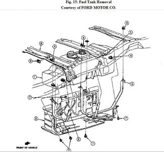
Removal & Installation (Ranger)
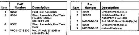
Drain fuel from fuel tank. Loosen fill pipe clamp. Remove bolts securing shield and bracket assembly to frame and remove assembly from vehicle. See Fig. 15 . Remove heat shield from vehicle. Support fuel tank. Remove bolts and nuts from rear strap and remove rear strap.
Remove bolt and nut from front strap and remove front strap. Lower tank. Remove feed hose at sender push connector. Remove return hose at sender unit push connector. Disconnect sender and fuel pump electrical connector. Remove fuel vapor hose from vapor valve. Lower tank from vehicle. To install, reverse removal procedure. Torque fuel tank strap bolts to specification.
Thursday, January 22nd, 2009 AT 5:50 PM