You need to remove the hub and press the joints with a ball joint press, Autozone will rent you the tool for free. remove lower ball joint first.
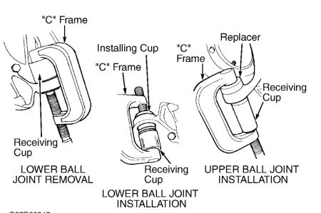
LOWER BALL JOINTS Removal & Installation Raise and support vehicle. Remove wheel assembly. Remove steering knuckle. See STEERING KNUCKLE . Place steering knuckle in a vise. Remove snap ring. Using Receiving Cup (D81T-3010- A) and C - Frame And Screw (T74P-4635-C), press upper ball joint from steering knuckle. See Fig. 7 . To install, clean steering knuckle ball joint bore. Reverse removal procedure.
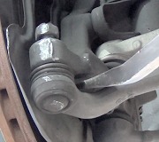
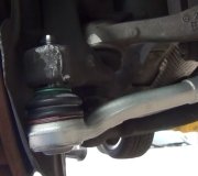
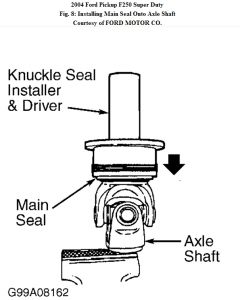
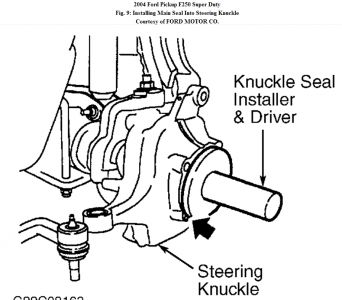
1. Raise and support vehicle. Remove wheel and tire assembly. Remove brake caliper, and wire caliper to frame. DO NOT hang by flexible brake hose. Remove caliper anchor plate. Remove brake rotor. Remove hub and wheel bearing assembly. See HUB & WHEEL BEARING . Remove axle. Using a drift, drive main seal out of steering knuckle. Remove the axle shaft and main seal. 2. Remove and discard tie rod ball joint cotter pin. Remove nut. Using Pitman Arm Puller (T64P- 3590-F), separate tie rod end from steering knuckle. Remove and discard upper ball joint cotter pin. Remove nut and insert. Remove lower ball joint nut and steering knuckle. Clean and inspect steering knuckle ball joint bores. Installation 1. Install steering knuckle onto the axle housing. Install nut on lower ball joint finger tight. Install insert and nut onto upper ball joint finger tight. Tighten lower ball joint, then upper ball joint retaining nuts. Install NEW cotter pin. DO NOT loosen nut to install cotter pin. Install tie rod end onto steering knuckle, tighten nut, and install NEW cotter pin. 2. Using Knuckle Seal Installer (205-429) and Driver (T83T-3132-A1), install NEW main seal onto axle shaft. See Fig. 8 . Position axle shaft into axle housing. Using Knuckle Seal Installer and Driver , install main seal into steering knuckle. See Fig. 9 . 3. To complete installation, reverse removal procedure. Perform wheel end vacuum leak test. See WHEEL END VACUUM LEAK TEST under ADJUSTMENTS & INSPECTION. Tighten remaining bolts and nuts. See TORQUE SPECIFICATIONS . Before driving vehicle, pump brake pedal several times to restore normal pedal position.
Disconnect wheel end vacuum hose. Connect vacuum pump to vacuum fitting on steering knuckle. Apply 15 in. Hg of vacuum to wheel end assembly. Observe vacuum gauge for 30 seconds. Wheel end should not leak more than 1/2 in. Hg in 30 seconds. If leak rate exceeds specification, check and repair as necessary. NOTE: When front hubs, axle shafts, or hub locks are removed, front wheel end assemblies must be checked for leaks.
Sunday, September 19th, 2010 AT 12:14 PM