Hi Greg,
Thank you for the donation.
Here are diagnostic procedures.
40) DTC P1130, P1150, P1131, P1151, P1132 Or P1152: HO2S Not Switching
DTCs P1131 and P1151 indicate air/fuel ratio is correcting rich for an overly lean condition.
DTCs P1132 and P1152 indicate air/fuel ratio is correcting lean for an overly rich condition.
DTCs P1130 and P1150 indicate fuel system has reached maximum compensation and HO2S is not switching at the adaptive limits. Possible causes are:
"� Fuel system malfunction.
"� EGR system malfunction.
"� Air intake or vacuum system leak.
"� Engine oil level too high.
"� Incorrect cam timing.
"� Restricted air cleaner.
"� Faulty PCV system.
"� Excessive internal engine wear.
Inspect engine for obvious defects in specified systems. Repair as necessary. If no faults are found, go to next step.
41) DTC P0171, P0172, P0174 Or P0175: HO2S Not Switching
DTCs P0171 and P0174 indicate air/fuel ratio is correcting rich for an overly lean condition.
DTCs P0172 and P0175 indicate air/fuel ratio is correcting lean for an overly rich condition.
Possible causes are:
"� Fuel system malfunction.
"� EGR system malfunction.
"� Air intake or vacuum system leak.
"� Engine oil level too high.
"� Incorrect cam timing.
"� Restricted air cleaner.
"� Faulty PCV system.
"� Excessive internal engine wear.
Inspect engine for obvious defects in specified systems. Repair as necessary. If no faults are found, go to next step.
42) Perform KOER Self - Test
Turn ignition off. Connect scan tool to DLC. Disconnect fuel vapor hose from intake manifold and plug fitting at intake manifold. Start engine, and operate at 2000 RPM for 5 minutes. Perform KOER ON-DEMAND SELF- TEST and proceed as follows:
"� If DTCs P1127, P1128 or P1129 are present, go to appropriate CIRCUIT TEST.
"� If DTC P0131 or P0151 is present in continuous memory, go to step 27).
"� If DTC P1130, P1131, P1150 or P1151 is present, go to step 43).
"� If DTC P1130, P1132 , P1150 or P1152 is present, go to step 49). If none of these DTCs are
present, proceed as follows:
"� If Continuous Memory DTC P1130, P1150, P0171, P0172, P0174 or P0175 is present, go to step 52).
"� If DTC P1132 or P1152 is no longer present, go to CIRCUIT TEST HX , step 22).
"� If DTC P1131 or P1151 is no longer present, go to CIRCUIT TEST HX , step 58).
"� On all others without reoccurring DTCs, fault is intermittent. Go to CIRCUIT TEST Z .
43) HO2S Circuit Test (With Lean DTCs)
Disconnect suspect HO2S. Turn ignition on. Using scan tool, select appropriate HO2S PID from PID/DATA monitor menu. Connect a jumper wire between HO2S SIG and VPWR terminals at suspect HO2S wiring harness connector. If spark occurs, remove jumper wire and go to step 47). If HO2S voltage is more than 1.3 volts, go to next step. If voltage is 1.3 volts or less, go to step 46).
44) Check Circuit Resistance
Turn ignition off. Disconnect PCM 104 -pin connector. Inspect connector for loose, damaged or corroded terminals. Repair as necessary. Install Breakout Box (014 - 00950). Connect PCM to breakout box. Measure resistance between negative battery terminal and SIG RTN terminal at suspect HO2S wiring harness connector. If resistance is less than 5 ohms, go to step 52). If resistance is 5 ohms or more, go to next step.
45) Check For Open Circuit
Turn ignition off. Disconnect PCM from breakout box. Measure resistance between test pin No. 91 (SIG RTN) at breakout box and SIG RTN terminal at suspect HO2S wiring harness connector. If resistance is less than 5 ohms, replace PCM. If resistance is 5 ohms or more, repair open circuit.
46) Check Resistance Of HO2S SIG & Ground Circuits
Turn ignition off. Install breakout box, leaving PCM disconnected. Disconnect suspect HO2S connector. Inspect connectors for loose, damaged or corroded terminals. Repair as necessary. Measure resistance of HO2S SIG circuit between HO2S SIG terminal at suspect HO2S wiring harness connector and appropriate HO2S SIG test pin at breakout box as
follows:
"� HO2S 11, test pin No. 60.
"� HO2S 21, test pin No. 87.
Also, measure resistance between SIG RTN terminal at suspect HO2S wiring harness connector and test pin No. 91 at breakout box. If all resistance readings are less than 5 ohms, go to next step. If any resistance reading is 5 ohms or more, repair open circuit.
47) Check HO2S Circuit For Short To Ground Measure resistance between test pins No. 24, 51, 77, 91 and 103 and appropriate HO2S SIG test pin at breakout box as follows:
"� HO2S 11, test pin No. 60.
"� HO2S 21, test pin No. 87.
If all resistance readings are more than 10,000 ohms, go to next step. If any resistance reading is 10,000 ohms or less, repair short circuit.
48) Check HO2S For Short To Ground
Reconnect HO2S connector. Measure resistance between test pins No. 91 and 103 and appropriate HO2S SIG test pin at breakout box as follows:
"� HO2S 11, test pin No. 60.
"� HO2S 21, test pin No. 87.
If any resistance reading is 10,000 ohms or less, replace HO2S. If all resistance readings are more than 10,000 ohms, replace PCM.
49) Check HO2S PID
Ensure ignition is off. Disconnect suspect HO2S connector. Turn ignition on. Using scan tool, select appropriate HO2S PID from PID/DATA monitor menu. If PID voltage is more than .2 volt, go to next step. If PID voltage is .2 volt or less, go to step 51).
50) Check For Short To Power
Turn ignition off. Disconnect scan tool from DLC. Disconnect PCM 104 -pin connector. Inspect connector for loose, damaged or corroded terminals. Repair as necessary. Install Breakout Box (014 - 00950), leaving PCM disconnected. Measure resistance between the following test pins at breakout box:
"� DTC P01130 and P01132 - Measure resistance between test pin No. 60 and test pins No. 71 and 93.
"� DTC P01150 and P01152 - Measure resistance between test pin No. 87 and test pins No. 71 and 94.
If all resistance readings are more than 10,000 ohms, replace PCM. If any resistance reading is 10,000 ohms or less, repair short to power.
51) Check For Shorted HO2S
Ensure suspect HO2S is disconnected. Turn ignition on. Using scan tool, select appropriate HO2S PID from PID/DATA monitor menu. If PID voltage is more than .45 volt, replace HO2S. If PID voltage is .45 volt or less, reconnect all connectors and go to next step.
52) Check Fuel Pressure
Release fuel system pressure. With ignition off, install fuel pressure gauge. Using scan tool, access OUTPUT TEST MODE. Command fuel pump on. Note fuel pressure. For fuel pressure specifications, see FUEL PRESSURE SPECIFICATIONS article. If fuel system pressure is not as specified, go to CIRCUIT TEST HC . If fuel system pressure is as specified, go to step 55).
53) Check System Ability To Hold Fuel Pressure
With fuel pressure gauge installed, cycle ignition from OFF to ON position 3 -4 times to pressurize fuel system (DO NOT start engine). If fuel pressure does not remain within 5 psi (34 kPa) of maximum pressure after one minute, go to CIRCUIT TEST HC , step 5). If fuel pressure remains within 5 psi (34 kPa) of maximum pressure reading for one minute, proceed as follows:
"� For no- start vehicles, go to step 55).
"� For DTCs P1130, P01150, P0171, P0172, P0174 and P0175, go to next step.
"� For HO2S DTCs displayed with misfire DTCs, go to step 56).
"� For all other DTCs, go to step 60).
54) Check Ability To Hold Fuel Pressure
With fuel pressure gauge installed, cycle ignition from OFF to ON position 3 -4 times to pressurize fuel system (DO NOT start engine). Note fuel pressure. If fuel pressure remains within 5 psi (34 kPa) of maximum pressure for at least 10 seconds, go to step 56). If fuel pressure drops more than 5 psi, go to step 58).
55) Check Ability Of Injectors To Deliver Fuel
With fuel pressure gauge installed, cycle ignition from OFF to ON position 3 -4 times to pressurize fuel system (DO NOT start engine). Note fuel pressure. Disconnect Inertia Fuel Shutoff (IFS) switch. Crank engine for 5 seconds. If fuel pressure remains within 5 psi (34 kPa) of maximum pressure, reconnect IFS switch and go to next step. If fuel pressure drops
more than 5 psi (34 kPa), electronic engine control system is not cause of no- start.
Reconnect all components. See TESTS W/O CODES - EEC-V article for further diagnosis of no- start.
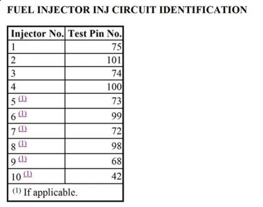
56) Check Fuel Injector & Circuit Resistance
Turn ignition off. Disconnect PCM 104 -pin connector. Inspect connector for loose, damaged or corroded terminals. Repair as necessary. Install Breakout Box (014 - 00950), leaving PCM disconnected. Measure and record resistance between suspect fuel injector circuit test pin and test pin No. 71 at breakout box. Refer to FUEL INJECTOR INJ CIRCUIT IDENTIFICATION table. Resistance should be 11 - 18 ohms. If resistance is not as specified, go to next step. If resistance is as specified, go to step 59).
NOTE: If misfire DTCs are present with fuel control DTCs, use misfire DTCs to determine which fuel injector circuits require testing.
57) Check Resistance Of Fuel Injector Circuit
Turn ignition off. Disconnect suspect fuel injector connector. Measure resistance between test pin No. 71 at breakout box and VPWR terminal at suspect fuel injector wiring harness connector. Also, measure resistance between fuel injector signal test pin(s) at breakout box and same fuel injector circuit terminal at suspect fuel injector wiring harness connector. If all resistance readings are less than 5 ohms, go to next step. If any resistance reading is 5 ohms or more, repair open circuit.
58) Check Fuel Injector Circuit For Short To Power Or Ground
Measure resistance between fuel injector test pin(s) and test pins No. 24, 71 and 103 at breakout box. Also, measure resistance between fuel injector test pin(s) at breakout box and chassis ground. If all resistance readings are more than 10,000 ohms, go to next step. If any resistance reading is less than 10,000 ohms, repair short circuit.
59) Check Fuel Injector Drive Signal
With ignition off, connect PCM to breakout box. Connect non-powered 12 -volt test light between suspect fuel injector test pin and test pin No. 71. Crank or start engine. If test light glows dimly, system is functioning properly. Reconnect all components and go to next step. If test light does not glow dimly (no light/bright light), replace PCM.
60) Check Fuel Injector Flow & Leakage
Turn ignition off. Remove breakout box. Reconnect PCM and fuel injector connector(s). Use Rotunda fuel injector tester from Fuel Tester Kit (113 -00114) to flow test fuel injectors. Follow injector tester instructions. If fuel injector flow or leakage rate is not okay, replace defective fuel injector(s). If flow rate for each fuel injector is okay, proceed as follows:
"� For DTCs P1131 and P1151, go to next step.
"� For DTCs P0171, P0174, P1130, and P1150, go to step 62).
"� For DTCs P1132 and P1152, go to step 65).
"� For DTCs P1172 and P1175, fault is intermittent. Go to CIRCUIT TEST Z .
61) Check Secondary Air Injection
If vehicle is not equipped with secondary air injection, go to next step. Turn ignition off. Disconnect secondary air injection hoses from engine and plug air injection ports (engine side). With engine at operating temperature, perform KOER ON-DEMAND SELF- TEST . If DTC P1131 or P1151 is present, reconnect air injection hoses and go to next step. If DTC P1131 or P1151 is not present, go to CIRCUIT TEST HM , step 7).
62) Check Air Induction System
Check air induction system for leaks. Check PCV system for leaks. Check vacuum hoses for damage and tight connections. Check intake manifold gaskets. If any faults are found, repair as necessary. If no faults are found, proceed as follows:
"� For Continuous Memory DTCs P0171, P0174, P1130 or P1150, fault is intermittent.
Go to CIRCUIT TEST Z .
"� For DTCs P1131 and P1130, or P1151 and P1150, go to next step.
63) Check Cylinder Compression
Using compression gauge, check cylinder compression. If cylinder compression is not okay, repair engine as necessary. If compression is okay, go to next step (DTCs P1130, P1131, P1150 and P1151) or step 65) (DTCs P1132 and P1152). If misfire DTCs are displayed with fuel control DTCs, go to CIRCUIT TEST HD , step 20).
64) Check HO2S Integrity
Any vacuum or air leaks can cause DTCs P1130, P1131, P1150, and P1151. Possible causes are:
"� Leaking vacuum actuators.
"� HO2S coated with contaminates.
"� Faulty EGR valve.
"� Faulty PCV system.
"� Unmetered air leaks between throttle body and MAF sensor.
"� Engine sealing problems (intake and IAC valve).
Turn ignition off. Inspect HO2S wiring harness for chafing, burned wires or other damage. Repair as necessary. Disconnect suspect HO2S connector. Connect DVOM between SIG RTN terminal and HO2S SIG terminal at suspect HO2S. Start engine and operate at 2000 RPM for 3 minutes. Perform KOER ON-DEMAND SELF-TEST while monitoring HO2S voltage. If HO2S voltage is more than .5 volt during or at end of test, go to step 70). If voltage is .5 volt or less, replace HO2S sensor.
65) Perform KOER Self - Test
Start engine, and warm it to normal operating temperature. Turn ignition off. Disconnect suspect HO2S. Connect a jumper wire between HO2S SIG terminal at suspect HO2S wiring harness connector and negative battery terminal. Perform KOER ON-DEMAND SELF- TEST . If DTC P1131 or P1151 is present, remove jumper wire and go to next step. If DTC P1131 or P1151 is not present, check PCM connector and repair as necessary. If connector
is okay, replace PCM.
66) HO2S Check
Leave HO2S disconnected. Connect DVOM between HO2S SIG terminal and SIG RTN terminal at suspect HO2S wiring harness connector. Disconnect any vacuum hose from vacuum tree. Start engine and operate at 2000 RPM. If DVOM reads less than .4 volt within 30 seconds, go to step 70). If DVOM does not read .4 volt within 30 seconds, replace
HO2S.
NOTE: A break in step numbering sequence occurs at this point. Procedure skips from step 66) to step 70). No test procedures have been omitted.
70) Monitor HO2S PID
Start engine and allow to idle. Ensure engine is at normal operating temperature. Using scan tool, select HO2S PID from PID/DATA monitor menu. Observe PID value while wiggling and bending wiring harness between HO2S and PCM. If PID voltage stays high (more than .45 volt) or stays low (less than .45 volt), isolate fault and repair as necessary. If PID voltage switches, go to next step.
71) Monitor HO2S PID During Test Drive
Using an assistant, test drive vehicle under various conditions while observing HO2S PID. If PID voltage switches from about .4 to .6 volt, system is okay and testing is complete. If voltage does not switch from about .4 to .6 volt, replace HO2S.
NOTE: A break in step numbering sequence occurs at this point. Procedure skips from step 71) to step 80). No test procedures have been omitted.
80) DTC P0136, P0156, P1137, P1138, P1157 & P1158
DTCs P0136 and P0156 indicate that output voltage of downstream HO2S is not within set limits. KOER DTCs P1137, P1138, P1157 and P1158 indicate lack of HO2S switching. Possible causes are:
"� Damaged wiring harness or connector.
"� Exhaust system leaks.
"� Contaminated or defective HO2S. Inspect for faults.
Repair as necessary. If no faults are found, go to next step (for DTCs P0136 and P0156) or step 82) (for DTCs P1137, P1138, P1157 and P1158).
81) Perform KOER Self - Test
Start engine, and operate at 2000 RPM for 3 minutes. Perform KOER ON-DEMAND SELF- TEST . If DTC P1137, P1138, P1157 or P1158 is present, go to next step. If specified DTCs are not present, fault is intermittent. Go to CIRCUIT TEST Z .
82) Check Exhaust System
Leaks in exhaust system between engine and end of catalytic converter can cause DTCs P0136 and P0156. Possible causes are:
"� Incorrect HO2S torque.
"� Exhaust system leaks.
Inspect exhaust system including catalytic converter and HO2S. Repair as necessary. If exhaust system is okay, go to next step.
83) Check HO2S SIG Circuit For Short Circuit
Turn ignition off. Ensure suspect HO2S is disconnected. Disconnect scan tool from DLC. Disconnect PCM 104 -pin connector. Inspect connector for loose, damaged or corroded terminals. Repair as necessary. Install Breakout Box (014 -00950), leaving PCM disconnected. Measure resistance between test pin No. 91 (SIG RTN) and appropriate HO2S SIG test pin and at breakout box as follows:
"� HO2S 12, test pin No. 35.
"� HO2S 22, test pin No. 61.
Also, measure resistance between appropriate HO2S SIG test pin and test pins No. 24 (PWR GND), 71 (VPWR), 90 (VREF) and 103 (PWR GND) at breakout box. If all resistance readings are more than 10,000 ohms, go to next step. If any resistance reading is 10,000 ohms or less, repair short circuit.
84) Check Ground Circuit Resistance
Measure resistance between HO2S SIG terminal at suspect HO2S wiring harness connector and appropriate HO2S SIG test pin at breakout box as follows:
"� HO2S 12, test pin No. 35.
"� HO2S 22, test pin No. 61.
Also, measure resistance between test pin No. 91 (SIG RTN) at breakout box and SIG RTN terminal at suspect HO2S wiring harness connector. If any resistance reading is 5 ohms or more, repair open circuit. If all resistance readings are less than 5 ohms, go to next step.
85) Check HO2S Circuit
Turn ignition off. Connect scan tool to DLC. Reconnect suspect HO2S and PCM connectors. Turn ignition on. Using scan tool, select appropriate HO2S PID from PID/DATA monitor menu.
"� DTCs P0136, P1137 and P1138 are for HO2S 12.
"� DTCs P0156, P1157 and P1158 are for HO2S 22.
If PID voltage is more than 1.5 volts, go to step 88). If PID voltage is 1.5 volts or less, go to next step.
86) Check Ground Circuit In PCM
Turn ignition off. Disconnect PCM wiring harness from breakout box. Measure resistance between test pins No. 103 (PWR GND) and No. 91 (SIG RTN) at breakout box. If resistance is less than 5 ohms, remove breakout box. Reconnect PCM wiring harness to PCM and go to next step. If resistance is 5 ohms or more, replace PCM.
87) Check HO2S PID
Connect a jumper wire between VPWR and HO2S SIG terminals at suspect HO2S wiring harness connector. Turn ignition on. Using scan tool, select appropriate HO2S PID from PID/DATA monitor menu. If PID voltage is more than 1.5 volts, replace HO2S. Perform HO2S MONITOR REPAIR VERIFICATION DRIVE CYCLE. See FUEL MONITOR OR HO2S MONITOR REPAIR VERIFICATION DRIVE CYCLE under DRIVE CYCLES under ADDITIONAL SYSTEM FUNCTIONS. If PID voltage is 1.5 volts or less, replace
PCM. Perform HO2S MONITOR REPAIR VERIFICATION DRIVE CYCLE.
88) Check For HO2S Voltage
Turn ignition on. Measure voltage between SIG RTN terminal at suspect HO2S wiring harness connector and negative battery terminal. Also, measure voltage between HO2S SIG terminal at suspect HO2S wiring harness connector and negative battery terminal. If any voltage reading is more than 1.5 volts, replace PCM. If both voltage readings are 1.5 volts
or less, replace HO2S.
NOTE: A break in step numbering sequence occurs at this point. Procedure skips from step 88) to step 100). No test procedures have been omitted.
100) KOER DTC P0127
DTC P0127 indicates that HO2S heater was not on during KOER self -test and testing of HO2S did not occur. Possible cause is cool exhaust system. Connect scan tool to DLC. Using scan tool, access all HO2S heater PIDs. If all PIDs indicate ON, repeat QUICK TEST . If any PIDs indicate OFF, operate engine until all PIDs are on. Repeat QUICK
TEST.
NOTE: A break in step numbering sequence occurs at this point. Procedure skips from step 100) to step 110). No test procedures have been omitted.
110) KOER P1128 & P1129
These DTCs indicate that during KOER self -test, one or both HO2S signals were crossed from bank to bank. DTC P1128 refers to HO2S in front of converter. DTC P1129 refers to HO2S behind converter. Possible causes for these faults are:
"� Crossed HO2S connectors.
"� Crossed HO2S wiring at HO2S connector.
"� Crossed HO2S wiring at PCM connector.
Turn ignition off. Disconnect suspect HO2S. Inspect connector for indication of crossed wires or incorrect installation. Repair as necessary. If no faults are found, go to next step.
111) Verify Proper HO2S SIG Pin Location
Disconnect PCM 104 -pin connector. Inspect connector for loose, damaged or corroded terminals. Repair as necessary. Install Breakout Box (014 -00950), leaving PCM disconnected. Disconnect both suspect HO2S connectors.
"� DTC P1128 is for HO2S 11 and 21.
"� DTC P1129 is for HO2S 12 and 22.
Measure resistance between HO2S SIG terminal at suspect HO2S wiring harness connector and appropriate HO2S SIG test pin at breakout box as follows:
"� HO2S 11, test pin No. 60.
"� HO2S 12, test pin No. 87.
"� HO2S 21, test pin No. 35.
"� HO2S 22, test pin No. 61.
If resistance is less than 5 ohms, fault is intermittent and cannot be duplicated at this time. If resistance is 5 ohms or more, HO2S wiring is crossed. Recheck all HO2S wiring pin locations at PCM and HO2S connectors. Repair as necessary.
Thursday, October 22nd, 2009 AT 11:24 AM