1994 Ford Bronco hard shifting

Tiny
SCOTT0024
  • MEMBER
  • 1994 FORD BRONCO
Transmission problem
1994 Ford Bronco V8 Four Wheel Drive Automatic

can anyone tell me the reset procedure for the psom, I dont have a ford service manual. And would be very greatful if someone can tell me hoe to reset the programable speedometer/ odometer module. On a 1994 ford bronco 4x4 e40d trans 5.8 lit
Do you
have the same problem?
Yes
No
Saturday, July 25th, 2009 AT 7:10 PM

12 Replies

Tiny
MERLIN2021
  • MECHANIC
  • 17,250 POSTS
What I did find for you is testing and repair instructions, Any codes?
SPEEDOMETER 1. Turn ignition on. 2. Observe odometer. If odometer display is on and digits appear normal, go to next step. If odometer display is not on and/or digits do not appear normal, go to step 6). 3. Observe odometer. If word ERROR appears, replace speedometer. If word ERROR does not appear, go to next step. 4. Test drive vehicle. If odometer accumulates mileage, go to step 9). If odometer does not accumulate mileage, go to next step. 5. Test drive vehicle. If indicated speed on speedometer increases with increasing vehicle speed, replace speedometer. If indicated speed does not increase, go to step 8). 6. Remove, check, and install fuses No. 8 and 17. If fuses are okay, go to next step. Replace fuses and repair shorted wires, if necessary. If speedometer and odometer still do not operate, go to next step. 7. Turn ignition on. Backprobe terminals No. 1 (Light Green/Yellow wire) and No. 3 (Pink/Black or White/Purple wire) of Programmable Speedometer/Odometer Module (PSOM) harness connector, located behind instrument cluster. If battery voltage does not exist, repair appropriate wire from fuse panel. With ignition off, measure resistance between terminal No. 2 (Black/White or Pink/Orange wire) and ground. If resistance is greater than one ohm, repair Black/White or Pink/Orange wire. 8. Set DVOM to measure AC voltage. Backprobe PSOM terminals No. 4 Red/Pink wire) and No. 5 (Light Green/Black wire). Test drive vehicle. If voltage increases smoothly from zero to approximately 3.5 volts as vehicle accelerates to 30 MPH, replace speedometer. If voltage does not increase as specified, repair speed sensor circuit. See chassis wiring diagram in WIRING DIAGRAMS. 9. Test drive vehicle. If indicated speed on speedometer increases with increasing vehicle speed, speedometer is okay. If operation is not as specified, replace speedometer.
Was this
answer
helpful?
Yes
No
+1
Sunday, July 26th, 2009 AT 8:16 AM
Tiny
SCOTT0024
  • MEMBER
  • 28 POSTS
I already replaced the fuses, but after that it says you must reset the psom referring to the 94 econoline/bronco service manual on page 13-01A-8.
The problem is I dont have the service manual. And I have no clue how to do the reset.
So you could not find it either.
Was this
answer
helpful?
Yes
No
Sunday, July 26th, 2009 AT 11:09 AM
Tiny
MERLIN2021
  • MECHANIC
  • 17,250 POSTS
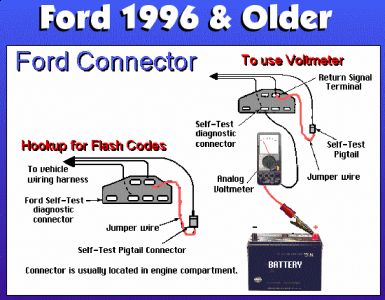
Havent found it, but to reset the PCM ground the STI under the hood on the left fender apron, when the check engine light starts flashing the codes, remove the jumper wire, theis clears the codes from memory.


https://www.2carpros.com/forum/automotive_pictures/62217_Pre_95_Ford_2.jpg


Also this:Programmable Speedometer/Odometer Module (PSOM) The PSOM receives input from rear brake anti-lock sensor, which is mounted on rear axle differential housing. Vehicle speed (mph) signal is output to PCM. PSOM failure may cause harsh engagements, firm shift feel and abnormal shift schedule. Unexpected downshifts may occur at closed throttle and abnormal TCC operation or engages at WOT. Transmission Control Indicator Light (TCIL) may flash. These RABS valces were notorious, check it for signal across the terminals with dvom set on ac volts, and spin the wheels, you should get a/c volts, the faster you spin, the higher the voltage. Also measure ohms at the sensor, should be 800-1400 ohms.
Diagnostic Aids Code 33 is generated by interrupted sensor signal or radio interference. The following conditions may be cause of problem: Ã Â Â Poor connections at rear wheel sensor. Ã Â Â Poor contact at ECU connector. Ã Â Â Open or shorted rear sensor coil. Ã Â Â Open or shorted circuit No. 518 (Light Green/Red). Ã Â Â Open or shorted circuit No. 519 (Light Green/Black). Ã Â Â Incorrect air gap. Ã Â Â Defective rear speed sensor. 1. Code 33: Check Rear Sensor Turn ignition off. Install Breakout Box. Measure resistance between pins No. 21 and 22. If resistance is not 800-1400 ohms, go to next step. If resistance is 800-1400 ohms, go to step 7). 2. Disconnect rear sensor wiring harness connector. Measure resistance between sensor terminals. If resistance is not 800-1400 ohms, replace sensor. If resistance is 800-1400 ohms, go to next step. 3. Check Circuit No. 518 Continuity Turn ignition off. Measure resistance between pin No. 22 and wheel sensor wiring harness connector Light Green/Red wire terminal. If resistance is not about zero ohms, repair circuit No. 518 (Light Green/Red). If resistance is about zero ohms, circuit is okay, go to step 4). 4. Check Circuit No. 519 Continuity Turn ignition off. Measure resistance between pin No. 21 and wheel sensor wiring harness connector Light Green/Black wire terminal. If resistance is not about zero ohms, repair circuit No. 519 (Light Green/Black). If resistance is about zero ohms, go to next step. 5. Check Circuit No. 518 Short To Ground Turn ignition off. Leave rear sensor wiring harness connector disconnected. Measure resistance between pins No. 1 and 22 at Breakout Box. If continuity is present, repair circuit No. 518 (Light Green/Red) short to ground. If continuity is not present, go to next step. 6. Check Circuit No. 519 Short To Ground NOTE: On some models, circuit No. 523 (Red/Pink) is used instead of circuit No. 518 (Light Green/Red). Turn ignition off. Leave rear sensor wiring harness connector disconnected. Measure resistance between pins No. 1 and 21 at Breakout Box. If continuity is present, repair circuit No. 519 (Light Green/Black) short to ground. If continuity is not present, go to next step. 7. Check Sensor Cable For Damage Inspect sensor cable for damage. Repair or replace as necessary. If cable is okay, problem is intermittent and cannot be located at this time. See INTERMITTENT DIAGNOSIS PROCEDURE.
Was this
answer
helpful?
Yes
No
+1
Sunday, July 26th, 2009 AT 4:43 PM
Tiny
SCOTT0024
  • MEMBER
  • 28 POSTS
I will run these test and let you know what I find, but if you find the procedure for the PSOM will you please let me know? Do you think the front wheel sensors can also cause the trans to shift irradically?

Thank you I will be in touch soon

Scott
Was this
answer
helpful?
Yes
No
-1
Monday, July 27th, 2009 AT 8:21 PM
Tiny
MERLIN2021
  • MECHANIC
  • 17,250 POSTS
More likley to be that raer sensor at the differential, Ford had some problems there. Start testing by ohming that sensor, 800-1400 ohms.
Was this
answer
helpful?
Yes
No
Tuesday, July 28th, 2009 AT 2:34 AM
Tiny
SCOTT0024
  • MEMBER
  • 28 POSTS
Did the ohm test and got o ohms, pulled sensor out and it came out with a long strand of copper. Installed new sensor and it shifted great. However the chattering noise was still there louder during idle, scrapping during driving range. Then the truck would not go at stop sign. Waited a few minutes and got it to go. But no reverse. I pulled trans out and found that the torque conv. Was the noise fluid had some metalic in it. Going to flush system before we install new torque conv. Do you have any thoughts or suggestions for me?
Was this
answer
helpful?
Yes
No
Sunday, August 2nd, 2009 AT 1:13 PM
Tiny
MERLIN2021
  • MECHANIC
  • 17,250 POSTS
Only if you found metal in the torque converter, it may need a tranny too. Metal came from someplace! Then flush the lines and cooler out real good.
Was this
answer
helpful?
Yes
No
Monday, August 3rd, 2009 AT 4:57 PM
Tiny
SCOTT0024
  • MEMBER
  • 28 POSTS
If shavings are in the pan, on the magnet. But how much is a bad sign
Was this
answer
helpful?
Yes
No
Monday, August 3rd, 2009 AT 10:49 PM
Tiny
SCOTT0024
  • MEMBER
  • 28 POSTS
Is there a way to bench test the trans, before I put it back in. Keeping in mind it did run to get it home. Just had no reverse.
Was this
answer
helpful?
Yes
No
-1
Monday, August 3rd, 2009 AT 11:41 PM
Tiny
MERLIN2021
  • MECHANIC
  • 17,250 POSTS
With special equiptment you can, but tranny shop may do a pressure test for you.
Was this
answer
helpful?
Yes
No
Tuesday, August 4th, 2009 AT 3:18 PM
Tiny
SCOTT0024
  • MEMBER
  • 28 POSTS
Installed new torque converter, the trans slid right up to the motor with less than a 1/4" gap between both. Tightened up the bolts then found the motor will not turn by hand. Loosened the bolts back just a little and the motor will turn by hand. What could be the problem

thanks
Scott
Was this
answer
helpful?
Yes
No
Sunday, January 3rd, 2010 AT 6:23 PM
Tiny
MERLIN2021
  • MECHANIC
  • 17,250 POSTS
Torque converter isnt in the tranny all the way, turn it while installing it.
Was this
answer
helpful?
Yes
No
Monday, January 4th, 2010 AT 2:31 AM

Please login or register to post a reply.

Sponsored links